Infrared support, I2c interface, C interface – Rainbow Electronics MAXQ3108 User Manual
Page 56: Figure 2. ir option on uart 0, Maxq3108 low-power, dual-core microcontroller
MAXQ3108
Low-Power, Dual-Core Microcontroller
56
______________________________________________________________________________________
Infrared Support
UART channel 0 on the MAXQ3108 contains a special
feature that eases its use with some infrared communi-
cation systems. In these systems, an asynchronous ser-
ial signal is used to on-off modulate a high-frequency
carrier signal. This modulated carrier is then used to
further modulate an IR beam. Because of the popularity
of infrared remote controls, the receivers for this sort of
modulated signal are readily available and inexpensive.
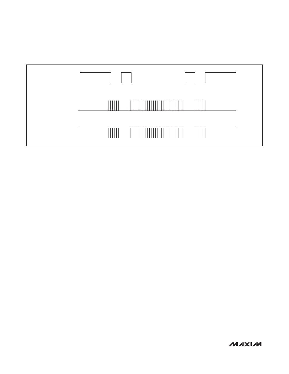
Signal Description: To convert an asynchronous sig-
nal into a signal suitable for IR transmission, the modu-
lated IR beam is typically turned on during “0” bit times,
and is turned off during “1” bit times. For conventional
serial data, this means that the IR beam is on only when
data is actually being transmitted, and is off at all other
times. See Figure 2.
Because drivers for the IR LED used as a transmitter
vary, there are two additional bits in the SMOD0 regis-
ter to configure the output signal. The first is the EPWM
bit. When set, the output of the lower half of timer 2 is
mixed with the transmitted serial data signal. The result-
ing waveform has the output frequency from the timer
when the data signal is low, and has either a low or
high level when the data signal is high.
The state of the output when the serial data signal is
high is set by the OFS bit in the SMOD0 register. When
the OFS bit is 0, the TxD pin is low when the serial data
signal is high; when the OFS bit is 1, the TxD pin is high
when the serial data signal is high.
The carrier frequency is generated by the low half of
timer 2 configured as two 8-bit timers. See the
Timer 2
and
Timer B
sections for more information about config-
uring this timer.
SPI
The MAXQ3108 contains an SPI peripheral that can be
configured as either a master or a slave. For information
on the SPI peripheral, refer to Section 11 of the
MAXQ
Family User’s Guide
. Note that the SPI peripheral is not
available when the ADC channels are used, since they
share pins.
I
2
C Interface
The MAXQ3108 contains an I
2
C peripheral. The I
2
C
bus is an 8-bit, bidirectional, 2-wire serial bus interface
with the following characteristics:
• Compliant with Philips Semiconductor I
2
C bus speci-
fication version 2.1 (2000).
• Information is transferred through a serial data bus
(SDA) and a serial clock line (SCL).
• Operates in either master or slave mode as transmit-
ter or receiver.
• Supports a multimaster environment.
• Supports 7-bit and 10-bit addressing modes.
• Data transfer rate of up to 100kbps in standard mode
and up to 400kbps in fast mode.
• On-chip filtering rejects spikes on the bus data line to
preserve data integrity.
• Supports maximum bus capacitance of 400pF.
A transfer sequence, in its simplest form, is composed
of a START bit (S), the slave address, a R/W bit, and an
address-acknowledge bit (A) followed by data, a data-
acknowledge bit (A), and a STOP bit (P). One party, the
master, initiates the sequence and governs the timing.
EPWM = 0
EPWM = 1, OFS = 0
EPWM = 1, OFS = 1
Figure 2. IR Option on UART 0