Timer 2, Timer b, Maxq3108 low-power, dual-core microcontroller – Rainbow Electronics MAXQ3108 User Manual
Page 61
MAXQ3108
Low-Power, Dual-Core Microcontroller
______________________________________________________________________________________
61
MREQ0 register. It decodes the request as a RAM
read request (0x02.) In response, it reads MREQ1
for the address to read.
4) The DSPCore completes the RAM read operation.
5) The DSPCore loads the results of the read to the
SRSP1 register.
6) The DSPCore loads 0x22 into the SRSP0 register.
This action simultaneously loads the response 0x02
into the response bits and sets the RSPSDV bit to
alert the UserCore that a response is pending.
7) The UserCore receives the response alert and
retrieves the response from the SRSP1 register. It
then clears the RSPSDV bit in the SRSP0 register.
8) The DSPCore sees that the RSPSDV bit is cleared. It
then clears the REQCDV bit in the MREQ0 register.
9) The UserCore sees the REQCDV bit go clear and is
now ready for the next request.
Timer 2
Timer 2 is a complex timing element designed for PWM
generation, IR generation and detection, and a variety
of other purposes. For information about this timer and
its properties, refer to Section 9 of the
MAXQ Family
User’s Guide
.
Timer B
The timer B peripheral is an enhanced timer type 1
(refer to the
MAXQ Family User’s Guide
for information
about type 0, type 1, and type 2 timers). It has many of
the features of the more complex type 2 timer, but with
an interface optimized for the 16-bit MAXQ architecture.
Timer B is managed through four 16-bit registers:
TB0CN is the configuration and status register; TB0V is
the current value of the timer; TB0R is the capture/reload
register; and TB0C is the compare register.
The bits of the configuration and status register are as
follows:
Bit 0: CP/RLB. If cleared to 0, TB0R functions as a
reload register. This means that TB0V is reloaded with
the appropriate value when overflow/underflow occurs.
(If counting up, TB0V is loaded with 0 when TB0V =
TB0R; if counting down, TB0V is loaded with TB0R
when TB0V = 0x0000.) If set, the TB0R captures the
value of TB0V when a falling edge is detected on TBB.
Bit 1: ETB. Enables all interrupts from timer B.
Bit 2: TRB. When set, timer B is allowed to run. When
cleared, the time is halted with its current state intact.
Bit 3: EXENB. Setting this bit enables capture/reload
functions on the TBB external pin. In capture mode, a
negative transition on this pin copies the current value
of the TB0V register into the TB0R register. In reload
mode, a negative transition on this pin resets TB0V to 0
(in upcount mode) or to TB0R (in downcount mode).
Bit 4: DCEN. When clear, the counter or timer counts
up. When set, the counter or timer counts either up or
down depending on the state of the TBB pin. In PWM
modes, the TBB pin is an output; in this case, when
DCEN is active the counter counts up to TB0R, then
counts down to 0 and repeats.
Bit 5: TBOE. When set, and when the timer is operating
in timer mode, this bit enables the output of the timer
onto the TB0A pin. When clear, the TB0A pin can be
used for an alternate function, or as an input to the
timer.
Bit 6: EXFB. This flag is used to trigger an interrupt on
any of the following conditions:
• The timer is configured as a timer in capture mode,
and a negative edge on the TBB pin is observed with
the TBB pin enabled.
• The timer is configured in reload mode and counts
up, and a negative edge on the TBB pin is observed
with the TBB pin enabled.
• The timer is configured to any PWM operating mode
and a negative edge on the TBB pin is observed with
the TBB pin enabled.
Additionally, if reload mode is in effect with no PWM
operating mode, the EXFB bit toggles on overflow/
underflow without generating an interrupt.
Bit 7: TFB. This flag is set on any overflow/underflow
event. It must be cleared by software.
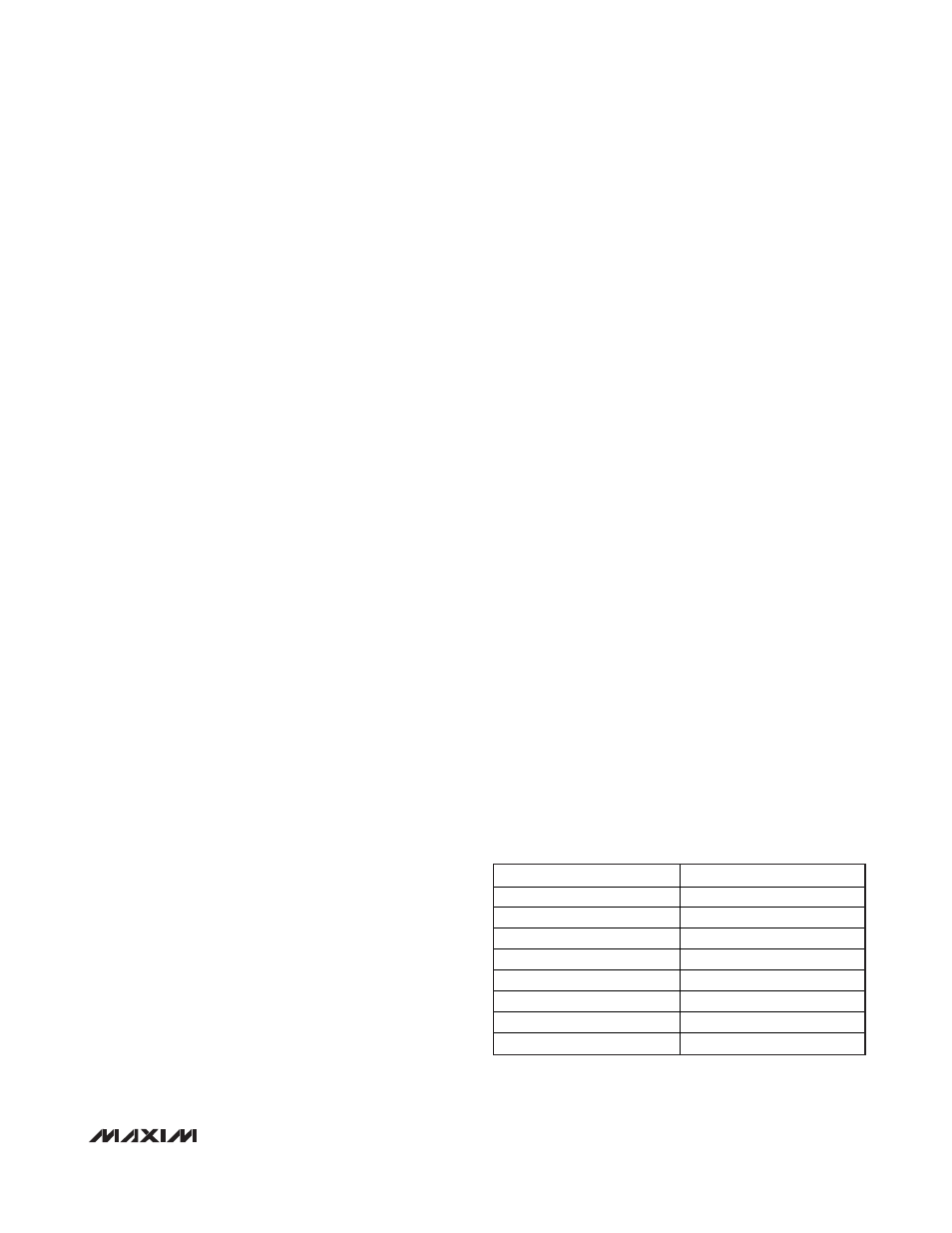
Bits 10 to 8: TBPS. These three bits define the
prescaler divisor:
VALUE
DIVISOR
000 1
001 4
010 16
011 64
100 256
101 1024
110 1
111 1