Adc inputs, Figure 3. adc bit stream decoder, Maxq3108 low-power, dual-core microcontroller – Rainbow Electronics MAXQ3108 User Manual
Page 58
MAXQ3108
Low-Power, Dual-Core Microcontroller
58
______________________________________________________________________________________
sent (and both SDA and SCL are low), the
I2CSTART bit is cleared. Note that the I2CSRI bit is
set in the I2CST register as well. That is because
the I
2
C peripheral sees its own START condition.
3) Load the command byte into I2CBUF. The com-
mand byte consists of the slave address and the
R/W bit. For this example, assume we wish to write
to slave address 0x30. The byte to be loaded in this
case is 0x60: the address shifted up by one posi-
tion and bit 0 (the R/W bit) set to a one.
4) Monitor the I2CTXI flag in the I2CST register. When
set, the I
2
C peripheral has finished sending the
command byte and has received an ACK or a NAK
from the remote device. Check the I2CNACKI flag
in the I2CST register to determine if an ACK or a
NAK was received. If set, the command was not
acknowledged. Clear these bits after they are test-
ed.
5) Set the I2CACK bit to 0 to acknowledge the first
byte.
6) Monitor the I2CRXI flag in the I2CST register. When
set, the I
2
C peripheral has finished receiving the
data byte and has sent the ACK. Read the data
from the I2CBUF register and clear the I2CRXI bit.
7) Clear the I2CACK bit to NAK the next received byte.
8) Monitor the I2CRXI flag in the I2CST register. When
set, the I
2
C peripheral has finished receiving the
data byte and has sent the NAK. Read the data
from the I2CBUF register and clear the I2CRXI bit.
9) Set the I2CSTOP bit in the I2CCN register. This
causes the MAXQ3108 to send the STOP
sequence. When this bit returns to 0, the STOP
sequence has been sent and the I
2
C bus is idle.
I
2
C Use Scenario: MAXQ3108 Slave Receives 2
Bytes from External Master
1) Set the I2CEN bit in the I2CCN register. This
enables the I
2
C peripheral.
2) Set the slave address in the I2CSLA register.
3) Monitor I2CST. As conditions change on the I
2
C
bus, they are reflected in the I2CST register. When
the I2CAMI bit is set, the address of the MAXQ3108
has been matched. The MAXQ3108 automatically
sends ACK when an address matches.
4) Set the I2CACK bit to 0 to ACK the received bytes.
5) Monitor the I2CRXI and the I2CSPI flags in the
I2CST register. When the I2CRXI bit is set, the I
2
C
peripheral has finished receiving the data byte and
has sent the ACK. Read the data from the I2CBUF
register and clear the I2CRXI bit.
6) When the I2CSPI flag is set, the I
2
C peripheral has
detected a STOP condition. No more characters are
to be expected.
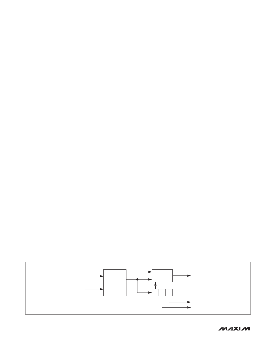
ADC Inputs
The MAXQ3108 contains six cubic sinc filters that
receive decoded bit streams from three Manchester
decoders. The ADC hardware is unique in that most of
the functions can be performed by either the UserCore
or the DSPCore. This section describes how these ADC
inputs are configured. See Figure 3.
The input to the Manchester decoder is a composite
signal consisting of two delta-sigma modulator chan-
nels and a synchronization signal. The decoder
extracts the clock and data and presents the signals to
a sync detector. This block searches for the synchro-
nization pattern and keeps a shift register in step with
the synchronized signal. When the sync detector is
asserting a lock indication, the recovered channel 0
and 1 outputs reflect two analog inputs at the ADC
modulator.
These recovered bit streams are presented to cubic
sinc filters for conversion to digital format. The filters
themselves have 24-bit resolution; however, the number
of bits that are actually significant depends directly on
the oversampling rate used in the filter control logic.
SYNC
DETECTOR
MANCHESTER
DECODER
CLOCK
MDINxP
LOCK
ΔΣ CH0
ΔΣ CH1
MDINxN
DATA
Figure 3. ADC Bit Stream Decoder