Maxq3108 low-power, dual-core microcontroller – Rainbow Electronics MAXQ3108 User Manual
Page 39
MAXQ3108
Low-Power, Dual-Core Microcontroller
______________________________________________________________________________________
39
Special Function Register Bit Descriptions (continued)
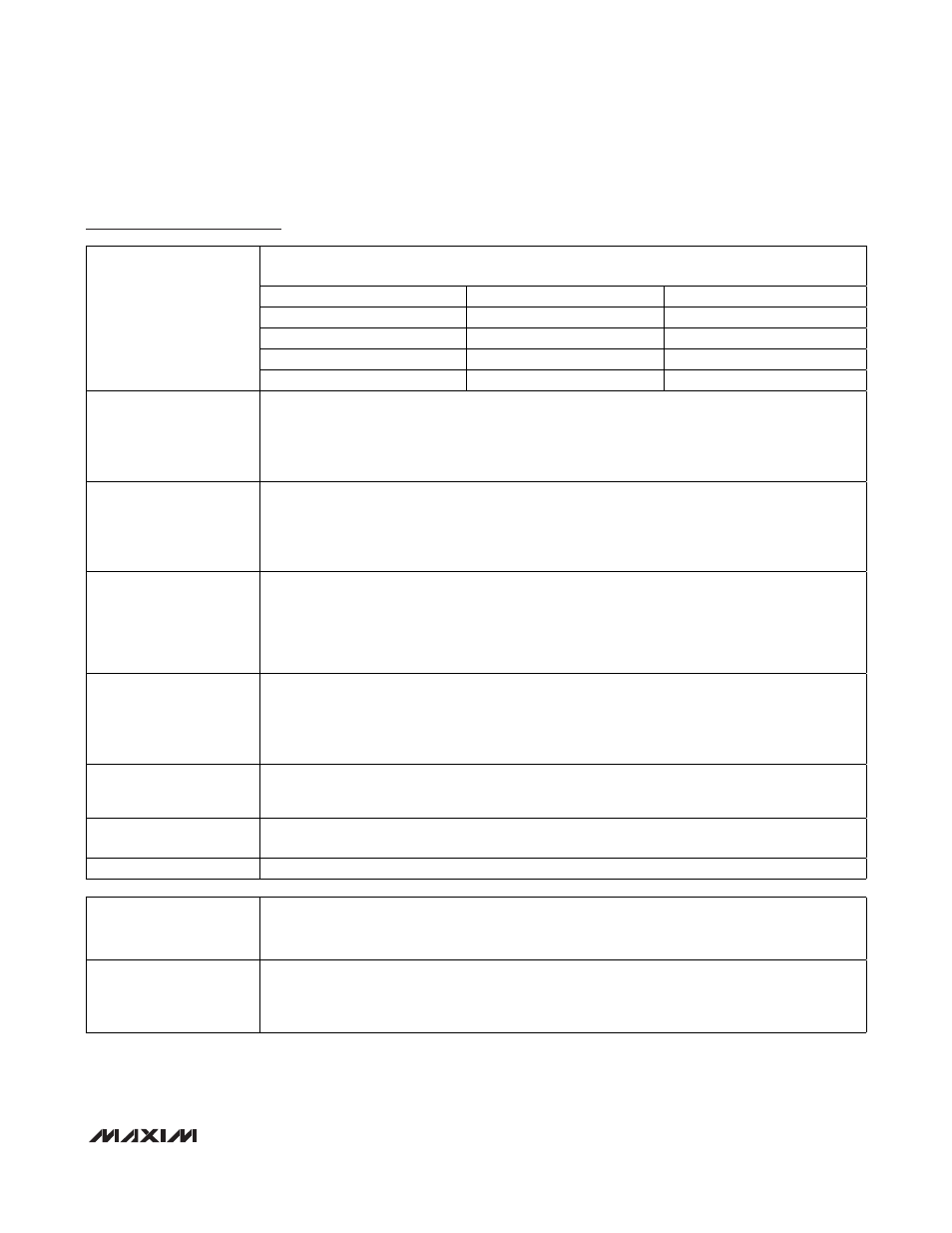
Multiply-Accumulate Negate. The state of the MSUB and MMAC bits determines the operation of
the hardware multiplier. The accumulator MC is formed by the MC2, MC1, and MC0 registers.
MSUB MMAC
OPERATION
0 0
MA
x
MB
0
1
MC + (MA x MB)
1 0
-
(MA
x
MC)
MCNT.2: MSUB
1 1
MC
-
(MA
x
MB)
MCNT.3: OPCS
Operand Count Select. This bit is used to select a number of operands for the multiplication
operation. When this bit is cleared to logic 0, an operation is initiated after two operands are written
to the MA and MB registers. When this bit is set to logic 1, an operation is initiated after an
operand is written to either the MA or the MB register. This bit has no meaning if the SQU bit is set.
This bit has no effect on division.
MCNT.4: SQU
Square-Function Enable. This bit is used to support hardware square function. When this bit is set
to logic 1, a square operation is initiated after an operand is written to either the MA or the MB
register. Writing data to either of the operand registers writes to both registers and triggers a square
calculation. Setting this bit to 1 also disables the OPCS function. When this bit is cleared to logic
0, the hardware square function is disabled. This bit has no effect on division.
MCNT.5: CLD
Clear Data Register. This bit is used to initialize the operand registers and the accumulator of the
multiplier. The contents of all five data registers and the OF bit are cleared to 0 and the sequence
counter is reset immediately after the CLD is set. This bit is cleared by hardware automatically. If
an operation is in progress (DIVSZ = 1) when this bit is set to 1, the operation is aborted and the
contents of all data registers and the OF bit are cleared to 0. Writing this bit to 0 causes no
operation.
MCNT.6: MCW
MC Register Write Select. The state of the MCW bit determines if a multiplication operation result
is placed into the accumulator register (MC):
If MCW is 0, the result is written to the MC register.
If MCW is 1, the result is not placed into the MC register and the content of the MC register is not
changed. This bit has no effect on division.
MCNT.7: OF
Overflow Flag. This bit is set to logic 1 when an overflow occurred for the last operation. This bit is
automatically cleared to 0 following a reset, starting a multiplier/division operation or the setting of
the CLD bit to 1.
MCNT.8: Reserved
Reserved. Do not write a 1 to this location. Functionally, this is the DIVE bit, however, there are
problems with the divide operation.
MCNT.[15:9]: Reserved
Reserved. Reads return 0.
MA (01h, 03h)
Multiplier Operand A Register
Initialization:
This register is cleared to 0000h on all forms of reset.
Read/Write Access:
Unrestricted read/write.
MA.[15:0]:
Multiplier Operand A Bit 15:0. This operand A register is used by the user software to load a 16-bit
value for a multiplier operation. Loading of the MA and MB registers initiates a selected multiplier
operation, dependent on the setting of the MMAC bit. The data type is determined by the SUS bit.
The result is stored to the MC register.