Pin description, Maxq3108 low-power, dual-core microcontroller – Rainbow Electronics MAXQ3108 User Manual
Page 7
MAXQ3108
Low-Power, Dual-Core Microcontroller
_______________________________________________________________________________________
7
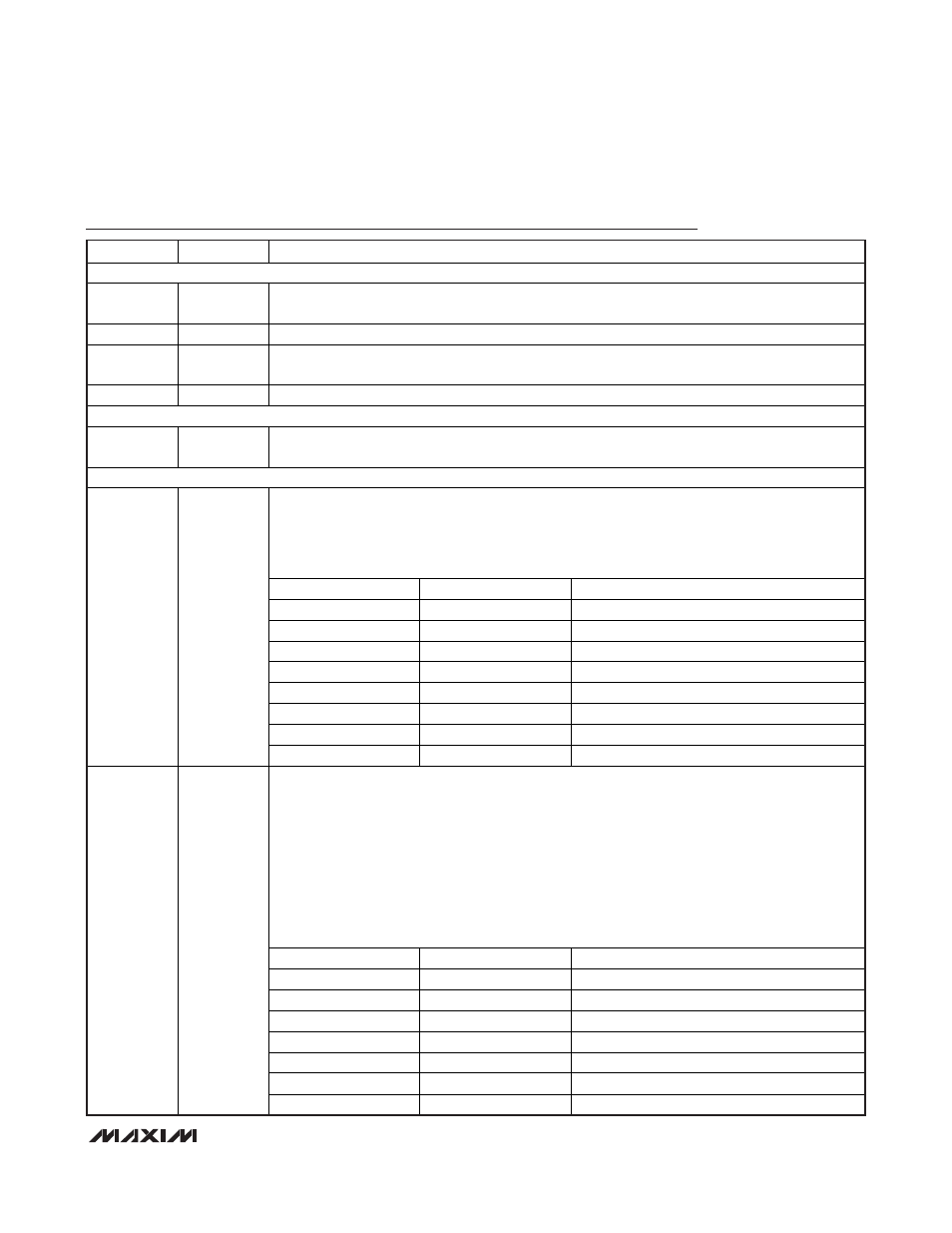
Pin Description
PIN
NAME
FUNCTION
POWER PINS
21 V
DD
Supply Voltage. Must be bypassed with a 4.7μF capacitor with ESR < 5
and a 0.1μF ceramic
capacitor.
17 GND
Ground
20 REGOUT
Regulator Output. 1.8V output. Must be connected to a 1μF low-ESR (< 1
) external ceramic chip
capacitor.
19 V
BAT
Battery Input for Backing Up the RTC
CLOCK PINS
15, 16
CX1, CX2
RTC Crystal Inputs. The RTC requires a 32.768kHz crystal to be connected in order to supply the
time base for the RTC. The 6pF load capacitors are included in the circuitry.
I/O PINS
Port 0. Port 0 functions as both an 8-bit I/O port and as a special function interface to the I
2
C
master and serial UARTs 0 and 1. All pins support external interrupt functionality. The default
reset condition of the pins is weakly pulled up (input). To drive output, either the port direction
register must be programmed to enable output or the alternate function module must be
configured to drive the pins. This port is accessible to the UserCore only.
PIN
PORT
ALTERNATE FUNCTION
2 P0.0
TXD0/INT0
3 P0.1
RXD0/INT1
4 P0.2
MDIN1N/T2P/INT2
5 P0.3
MDIN1P/T2PB/INT3
6 P0.4
SDA/INT4
7 P0.5
SCL/INT5
23 P0.6
TXD1/INT6
2–7, 23, 22
P0.0–P0.7
22 P0.7
RXD1/INT7
Port 1. Port 1 functions as both a 6-bit I/O port and as a special function interface to the JTAG
compatible test access port (TAP), the RTC square-wave output, and as the input/output to and
from timer B. All pins support external interrupt functionality. The default reset condition of pins
P1.0–P1.3 is the JTAG functions. To use the 4-bit port as standard GPIO, the TAP must be
disabled by user code. This port is accessible to the UserCore only.
Active-Low Reset (
RST). The RST pin recognizes external active-low reset inputs and employs
an internal pullup resistor to allow for a combination of wired-OR external reset sources. An RC is
not required for power-up, as this function is provided internally. The RST pin function is enabled
on power-on reset. It is critical that this pin not be held low externally after a power-on reset or the
device cannot exit the reset state.
PIN
PORT
ALTERNATE FUNCTION
10 P1.0
TMS/INT8
11 P1.1
TCK/INT9
12 P1.2
TDI/INT10
13 P1.3
TDO/SQW/INT11
14 P1.4
TBB
18 P1.5
TBA
10, 11, 12,
13, 14, 18,
24
P1.0–P1.6
24 P1.6
RST