Assembly – Grain Systems Bucket Elevtors, Conveyors, Series II Sweeps PNEG-1579 User Manual
Page 27
Assembly
27
PNEG-720-G2 12" & 16" Series II Sweep
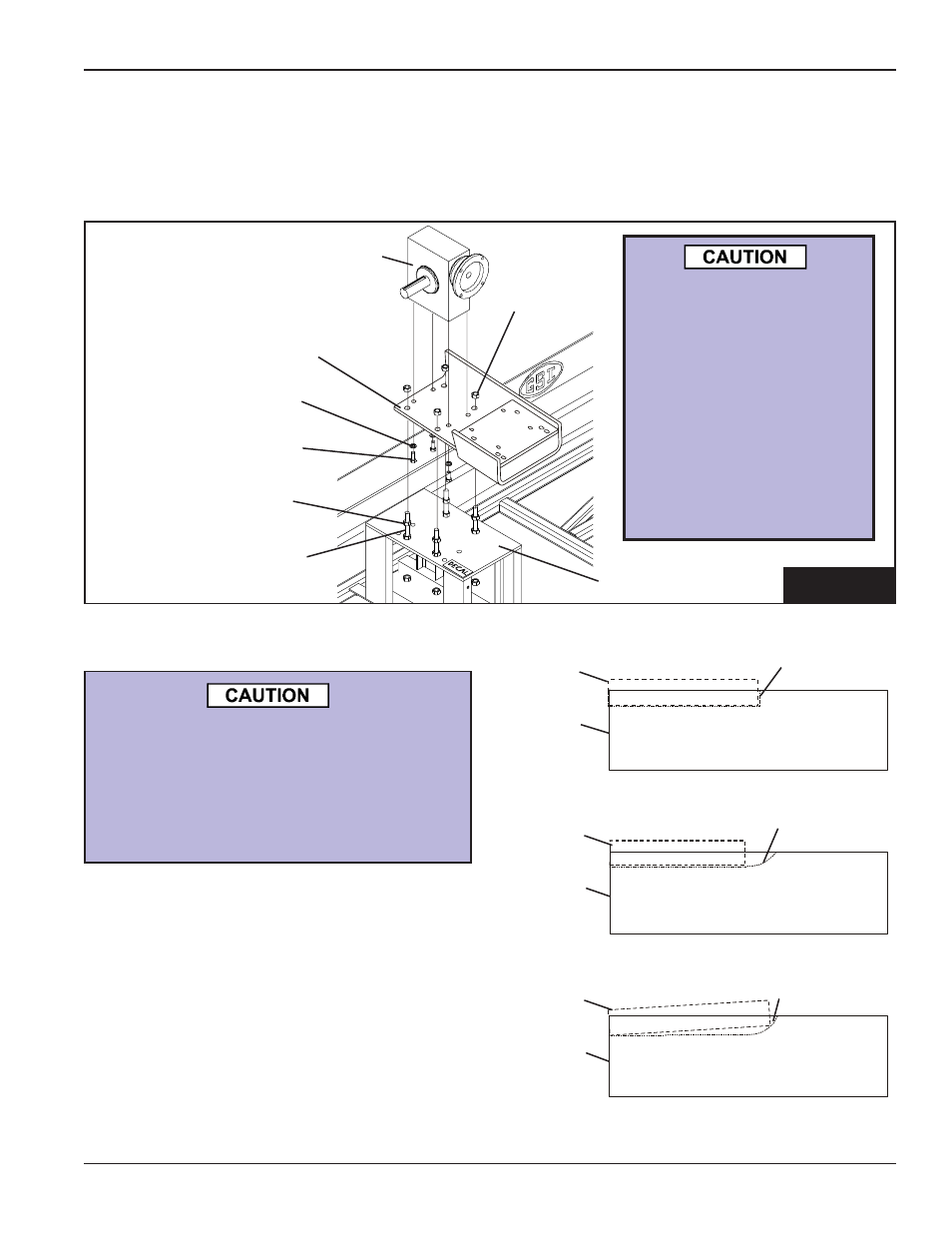
A. Attach the C-Face reducer to the mounting plate using four (4) 1/2"-13 x 1-1/4" hex bolts and
lockwashers.
B. Fasten the mounting plate to the tail section plate using four (4) 5/8"-11 x 6" all-thread rods and
sixteen (16) hex nuts. Adjust the mounting plate as close as possible to the tail section plate.
hex nut
lockwasher
C-Face Reducer
reducer
mounting plate
5/8" x 6" all-thread rod
hex nut
1/2"-13 x 1 1/4" hex bolt
tail section plate
FIG. 7
8-A. KEY ALIGNMENT
7. INSTALL REDUCER MOUNTING PLATE & REDUCER
The gear reducer is NOT
filled with oil from the
factory. For gear re-
ducer specifications
and oil fill recommenda-
tions, refer to the own-
ers manual supplied
with the reducer or the
lubrication information
in the maintenance
section of this manual.
All keys should be parallel to the drive
shaft. If the key is not straight (parallel)
the gearbox quill sleave will crack.
THIS TYPE OF DAMAGE IS NOT
COVERED BY WARRANTY.
1. Place key in keyway on drive shaft.
2. Make sure key is flat (parallel to drive shaft) in
keyway as in Figure 8A-1 and 8A-2. NOT like
Figure 8A-3.
3. Line up keyway on shaft with keyway on reducer
and insert shaft into motor. (See Figure 8A-4 on
page 30.)
Key
Drive
Shaft
FIGURE 8A-1
Key correctly positioned in a straight routed
keyway. (Profiled keyway)
Keyway
Key
Drive
Shaft
FIGURE 8A-2
Key correctly positioned in a scalloped
routed keyway. (Sled runner keyway)
Keyway
Key
Drive
Shaft
FIGURE 8A-3
Key INCORRECTLY positioned in a
scalloped routed keyway. DO NOT install
key in this position.
Keyway