Menu lock-out protection – Ohaus GT Series Electronic Balance User Manual
Page 73
34
MENUS
MENU LOCK-OUT PROTECTION
MENU LOCK-OUT PROTECTION
MENU LOCK-OUT PROTECTION
MENU LOCK-OUT PROTECTION
MENU LOCK-OUT PROTECTION
Access to the
Calibration
Calibration
Calibration
Calibration
Calibration
,
User
User
User
User
User
,
Setup
Setup
Setup
Setup
Setup
and
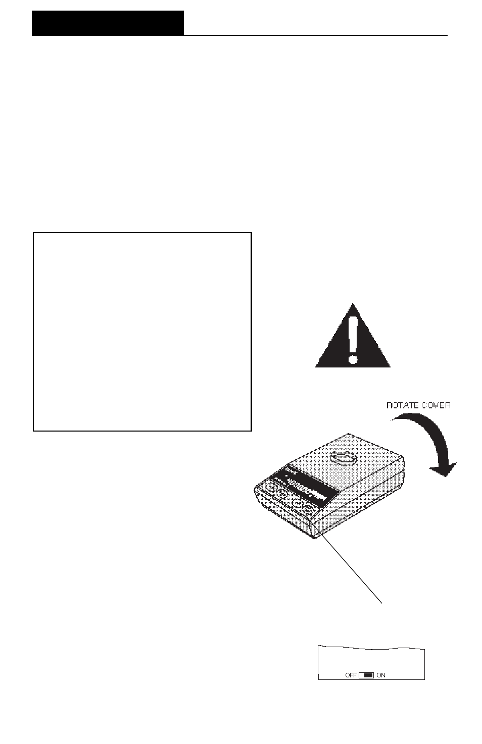
menus, can be disabled using
the Lockswitch located on the PC board
inside the balance. The Lockswitch locks
out menus selected in the Lockswitch
menu. The default setting for the Lock-
switch is OFF.
1.
Turn the display off and unplug the
power cord.
2.
Remove the platform and platform
support.
3.
Remove the two (2) cover screws
and tilt the cover towards the right
side of the balance.
4.
The menu Lockswitch is located on
the front of the PC board. The OFF
position is to the left facing the front
of the balance.
5.
Select the desired position on the
Lockswitch and reassemble the bal-
ance.
LOCKSWITCH
LOCATED INSIDE OF
BALANCE
WARNING
•
To avoid shock hazards, always be
certain that the power cord is discon-
nected BEFORE removing the bal-
ance cover.
•
Even though the balance may have
been switched OFF, high voltage is
present inside the balance as long as
the power cord is connected.
•
A power cord has been furnished with
the balance. DO NOT use any other
type of power cord other than the one
furnished.
DO NOT create a safety hazard by
defeating the grounding feature.