M&C TechGroup SP2400-H Operator's manual User Manual
Page 40
40
Gas sampling and gas conditioning technology
2-1.1-ME
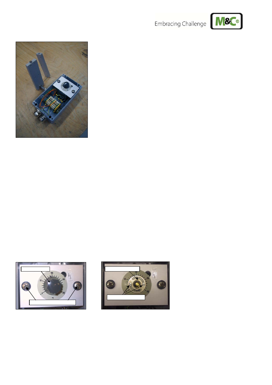
Figure 22
Dismounted electrical connection box with heating cartridge and thermostat sensor
Loosen the cable gland C (figure 21) for the heating cartridge and the capillary tubes of the thermo-
stat.
Disconnect the electrical connection lines of the heating cartridge and the termostat from the termi-
nal block (figure 9).
Take off the turning knob from the thermostat. Remove the 2 locking screws D (figure 23) beneath.
Take off the locking screws E (figure 23) of the thermostat retaining plate.
Draw the heating cartridge through the cable gland C (figure 21) out of the connection box.
Draw out the thermostat sensor through the cable gland in the opposite direction.
Mount the new thermostat and lead the thermostat sensor from inside through the cable gland.
Feed the new heating cartridge from outside through the cable gland.
Connect the electrical cables according to the connection plan (figure 9).
Mount the complete unit to the probe again.
The thermostat is equipped with a mecanical stop that limits the maximum temperature adjustable via
the turning knob.
When mounting the thermostat pay attention that the mecanical stop is mounted so that the arrow on
the metallic ring shows to the desired maximum temperature. (Standard adjustment 190°C).
Figure 23
Adjustment of the mechanical stop at the thermostat controller
If you use gas sample probes with temperature sensor (PT100 or thermoelement) instead of the ther-
mostat, lead the sensor connecting cable with the heating cartridge through the cable gland. In order
to do this, put the connecting cable into the corrugation of the sealing rings and the two metal rings.
Adjusting knob
Mechanical stop
Locking screws D
Fixing screws E