M&C TechGroup SP2400-H Operator's manual User Manual
Page 15
2-1.1-ME
Gas sampling and gas conditioning technology
15
N O T E !
The equipment should be stored in a protected, frost-free room!
13
PREPARATION FOR INSTALLATION
Select the optimal sampling point in accordance with the generally applicable guidelines or consult
the competent persons.
Locate the sampling point in such a way that there is adequate space for inserting and removing
the probe and pay attention to the insertion length of the probe tube.
Make certain that the probe is easily accessible so that you can carry out any subsequent mainte-
nance work without trouble.
Locate the probe connections in such a way that the connections' temperature is always above the
acid dew point in order to avoid corrosion and blockage problems. If this is not possible, a heated
SP35/SP30
probe tube is recommended for cold connections.
If the ambient temperature in the area of the connections is >80°C as a result of radiated heat, then
a radiated-heat deflector must be mounted to protect the probe.
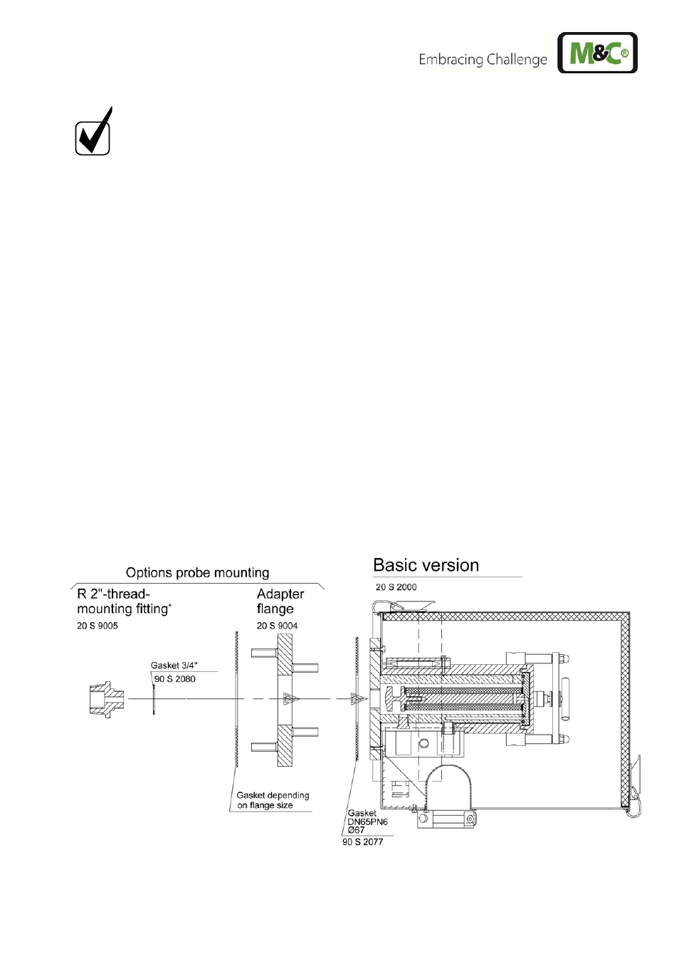
The connection's mounting flange connection should comply with DN65 PN6. If other connection
sizes are required, a special adapter flange /S010 can be supplied as an option. Instead of flange
connection mounting, the probe can also be mounted using an R2" adapter on a corresponding
threaded sleeve connection. This adapter can be supplied. The necessary minimum flange size
and the minimum connection diameter depends on the diameter of the probe tube or prefilter used.
Figure 2
Mounting possibilities SP2000..., SP2300-H, SP2400-H