M&C TechGroup SP2400-H Operator's manual User Manual
Page 22
22
Gas sampling and gas conditioning technology
2-1.1-ME
The temperature-resistant, stainless steel connectors supplied by M&C have a double ferrule sys-
tem to ensure reliable sealing. After tightening the nuts of these connectors by hand, they should
then be tightened exactly 1¼ of a turn using a flat spanner and are then properly mounted.
Close mounting bracket . In case of larger sample line diameters, it may be necessary for the
central mounting of the sample line to loosen the two screws and move the small mounting angle
of the mounting bracket and then re-tighten them.
Now place the heat conducting jaws around the sample gas connection in the retaining slot and
fix with the knurled nut .
C A R E !
Never operate probe without heat conducting jaws because of the result-
ing cold bridge blocking of connector and line is to be expected !
14.5
CONNECTION OF OPTION TEST GAS FEEDING OR BLOW BACK LINE
When using the options /R or 3-way ball valve option /3VA or /3VA320 , the corresponding
tubes for test gas feeding or blow back are connected by means of a tube connection on the re-
spective 6mm tube socket below the probe housing.
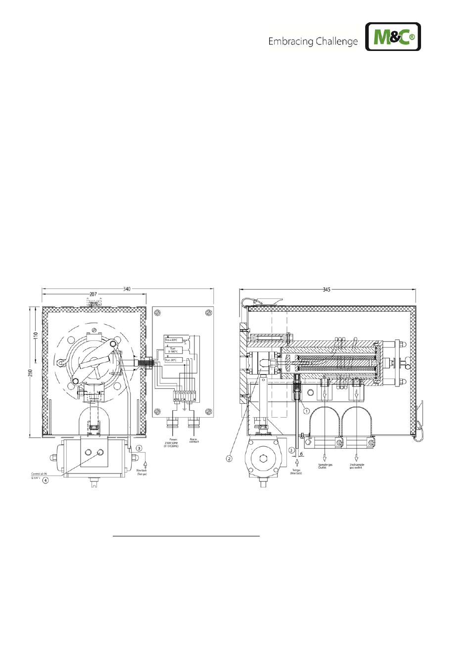
Figure 8
Connection test gas feeding or blow back line
With option -H320/C it is possible to feed test gas via the standard connection for a 6mm tube that
is equipped with a blind cap for the measuring operation. It is placed directly below the heat con-
ducting jaws. For the connection of the calibration gas line, the blind cap must be removed. By
means of the union nut that is attached to the consignment, the calibration gas line can be con-
nected.
A T T E N T I O N !
After the test gas feeding being finished, the connection must be shut
again with the blind cap because otherwise this connection would aspi-
rate secondary air and falsify the measuring result !