M&C TechGroup SP2400-H Operator's manual User Manual
Page 25
2-1.1-ME
Gas sampling and gas conditioning technology
25
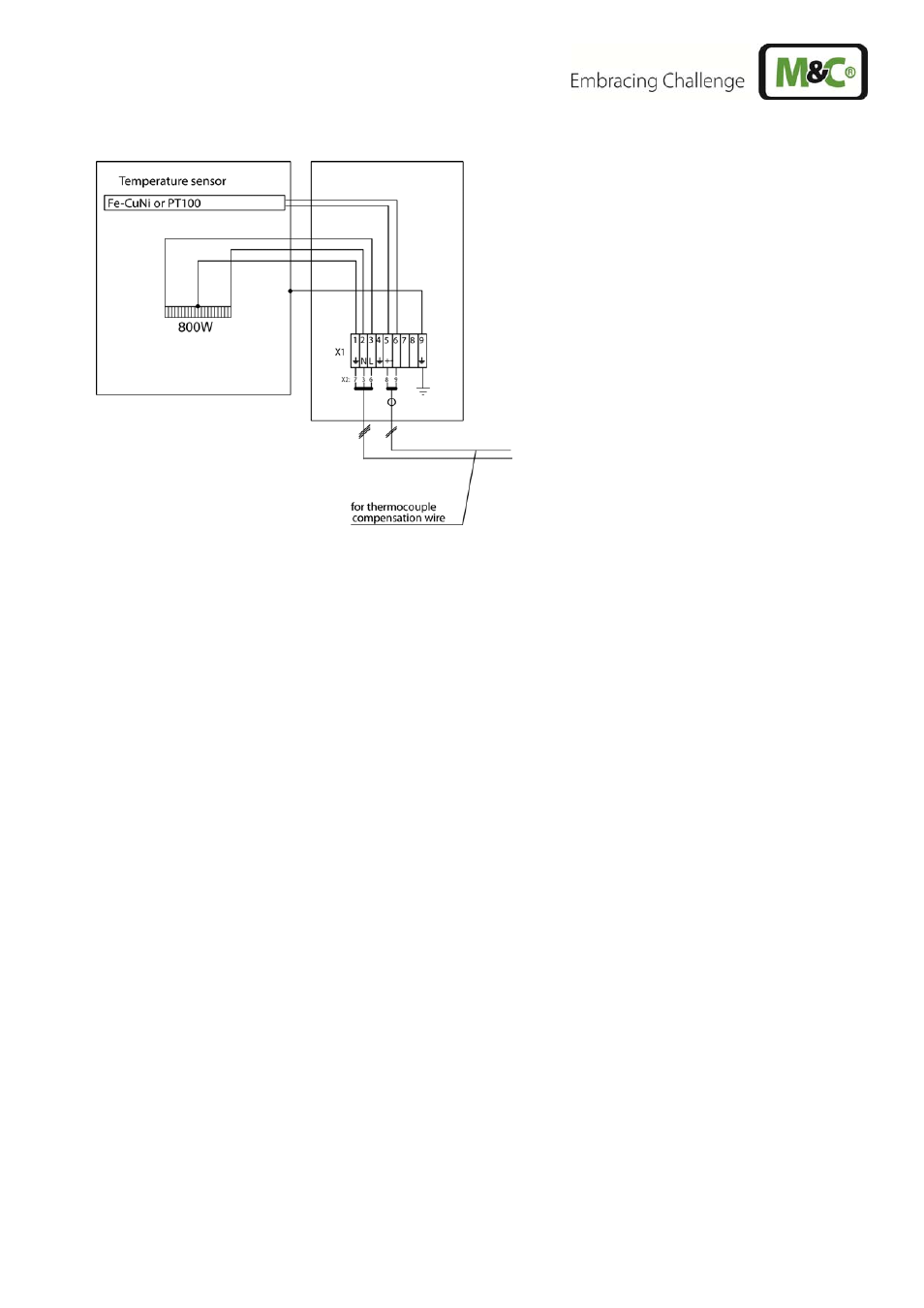
Figure 10
Electrical connection of external temperature controller e.g. 70304G
The electrical connection of the temperature regulator 70304G is effected according to the connection
plan (figure 11) and as described in the following:
Unscrew and remove the housing lid.
Introduce the mains cable (min. 3 x 1,5 mm
2
, clamping range 6-12mm) through the left cable
gland M20x1,5 of the regulator and connect it to the respective terminals.
Introduce the cable for the alarm contact (clamping range 6-12mm) through the right cable gland
M20x1,5 and connect it to the repective terminals.
In case the temperature regulator 70304G is attached as separate unit, the probe has additionally to
be connected with the regulator, according to figure 10 and the following description:
Introduce the power cable for the sample gas probe (min. 3 x 1,5 mm
2
, clamping range 6-12mm)
through the second cable gland M20x1,5 of the regulator and connect it to the respective terminals.
Introduce the temperature sensor cable (clamping range 6-12mm) through the third cable gland
M20x1,5 of the regulator and connect it to the respective terminals.
Screw the lid on the housing again.
C A R E !
If not all cable glands are used for the electrical connection of the temper-
ature regulator, the remaining ones must be shut in order to guarantee the
tightness of the housing.