M&C TechGroup SP2400-H Operator's manual User Manual
Page 18
18
Gas sampling and gas conditioning technology
2-1.1-ME
14.2
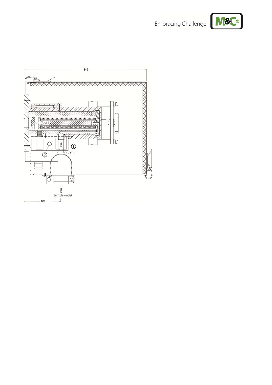
MOUNTING OF THE SCREWED CONNECTOR AT THE SAMPLE OUTLET
Remove heat conducting jaws at the sample outlet after loosening the knurled nut .
Figure 5
Mounting of screwed connector at sample outlet
In order to connect the sample line, screw in a suitably sized threaded connector with a ¼"-NPT
connecting thread using PTFE sealing tape.
For option second sample outlet SP2000/2x screw in two suitably sized threaded connectors with a
¼"-NPTa.
For option high heating -H320/C a 6mm pipe socket is welded on and a tube connector for 6mm
tube connection (optional 8mm) is supplied.
Remount heat conducting jaws and tighten knurled nut.
A T T E N T I O N !
Check tightness of the tube connections!
C A R E !
Never operate probe without heat conducting jaws because of the result-
ing cold bridge blocking of connector and line is to be expected !
14.3
MOUNTING OF PROBE WITH SAMPLE TUBE OR PREFILTER
Basically it is advantageous if the probe is built into the process with a lower downward inclination.
This mounting position is absolutely necessary if the SP32 sample tube is used for sampling e.g. after
wet scrubbers, so that separated liquid drops can flow back to process.