M&C TechGroup SP2400-H Operator's manual User Manual
Page 11
2-1.1-ME
Gas sampling and gas conditioning technology
11
11
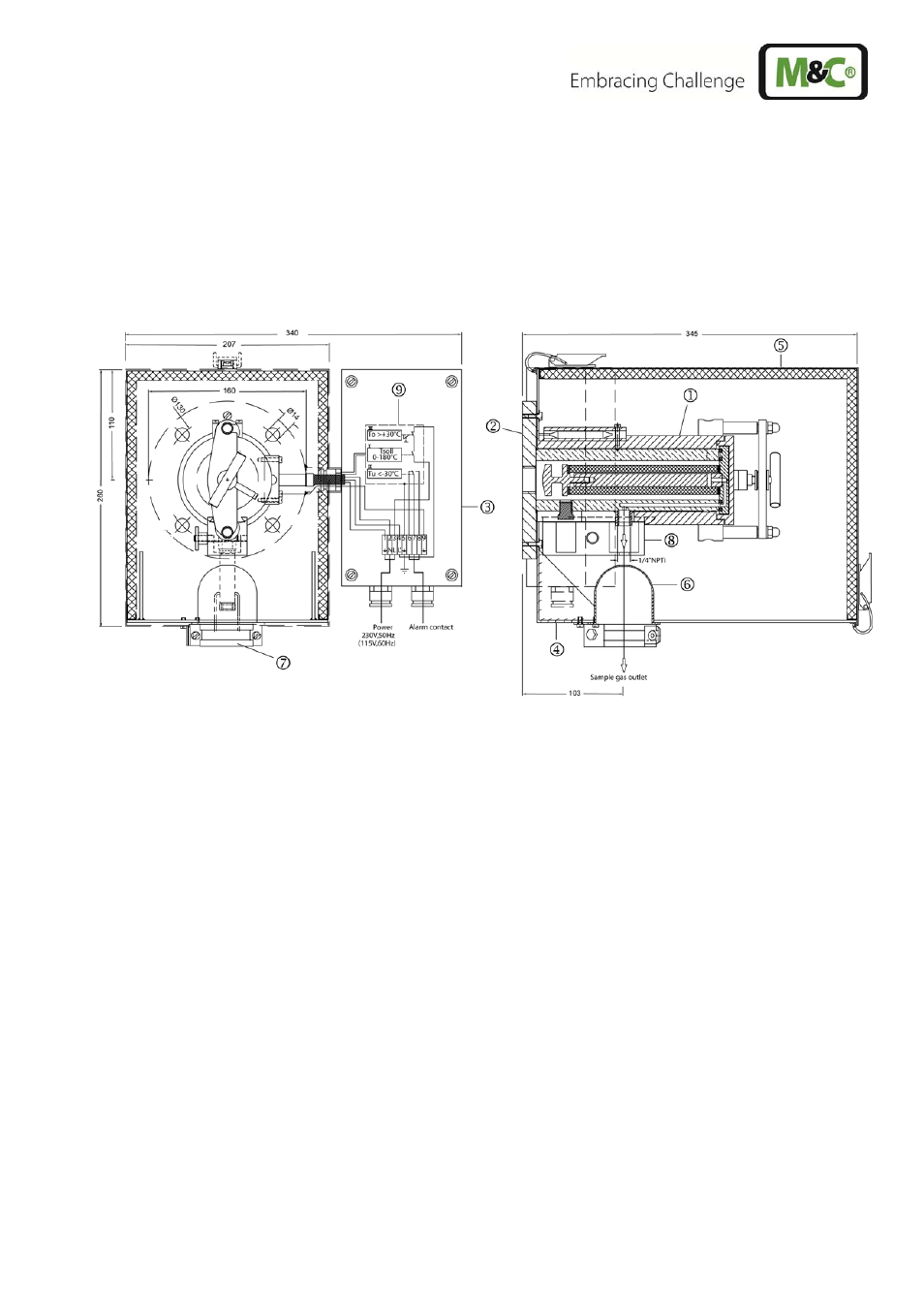
PROBE DESIGN OF THE HEATED VERSION
A complete gas sample probe consists of the heated filter part and a sample tube or prefilter. The filter
housing with its all-round heating element forms a unit with the standard mounting flange DN65
PN6 and the laterally mounted electrical connection box .
The heat-insulated shield is mounted on the stainless steel angle sheet which is mounted on the
mounting flange. It is secured with 2 pressure clamps. The cover ensures a uniform distribution of heat
over the probe heater and at the same time serves as protection against weather and accidental con-
tact.
Figure 1
Design of basic version SP2000-H
11.1
SAMPLE GAS CONNECTION
The connecting clamp for attaching heated M&C sample lines with external dimensions of between
40mm and 50mm is located at the aperture on the underside of the angle sheet, which is closed with a
silicon lid . The clamp is mounted on an adjustable mounting bracket which allows adjustment for
various sample line diameters.
The standard probe's sample gas outlet connection has a ¼" NPT internal thread to which the cus-
tomer must connect a suitable size of temperature resistant and threaded connector to connect the
sample line in a gas tight manner. These connectors can be supplied by M&C.
In the high-temperature version -H320/C..., the sample gas outlet connection is fitted with a welded 6
mm threaded pipe connection (optional 8mm).
After the threaded pipe connector and sample line have been mounted, the sample gas outlet connec-
tion is enclosed in special heat-conducting jaws in order to avoid temperature failures in the critical
connection areas. The size of the heat-conducting jaws allows connection joints up to an external pipe
dimension of 10mm.