6 ospf virtual-links, Figure 125 ospf virtual link – ZyXEL Communications GS-4012 User Manual
Page 238
Chapter 28 OSPF
GS-4012F/4024 User’s Guide
238
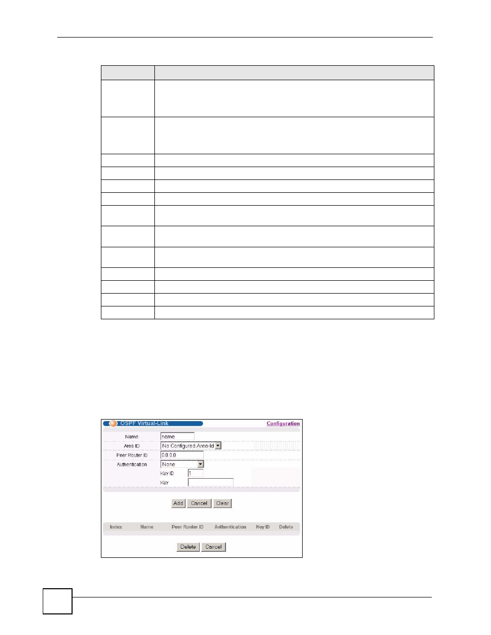
28.6 OSPF Virtual-Links
Configure and view virtual link settings in this screen. See
information on OSPF.
In the OSPF Configuration screen, click Virtual-Link to display the screen as shown next.
Figure 125 OSPF Virtual Link
Priority
The priority you assign to the interface is used in router elections to decide which
router is going to be the Designated Router (DR) or the Backup Designated Router
(BDR). You can assign a number between 0 and 255. A priority of 0 means that the
router will not participate in router elections.
Add
Click Add to save your changes to the Switch’s run-time memory. The Switch loses
these changes if it is turned off or loses power, so use the Save link on the top
navigation panel to save your changes to the non-volatile memory when you are done
configuring.
Cancel Click
Cancel to start configuring the above fields again.
Clear
Click Clear to set the above fields back to the factory defaults.
Index
This field displays the index number for an interface.
Network
This field displays the IP interface information.
Area ID
This field displays the area ID (that uses the format of an IP address in dotted decimal
notation) of an area to associate the interface to that area.
Authentication This field displays the authentication method used (Same-as-Area, None, Simple or
MD5).
Key ID
When the Authentication field displays MD5, this field displays the identification
number of the key used.
Cost
This field displays the interface cost used for calculating the routing table.
Priority
This field displays the priority for this OSPF interface.
Delete
Click Delete to remove the selected entry from the summary table.
Cancel
Click Cancel to start configuring the above fields again.
Table 90 OSPF Interface (continued)
LABEL
DESCRIPTION