Texas Instruments TSB12LV26 User Manual
Page 84
6–2
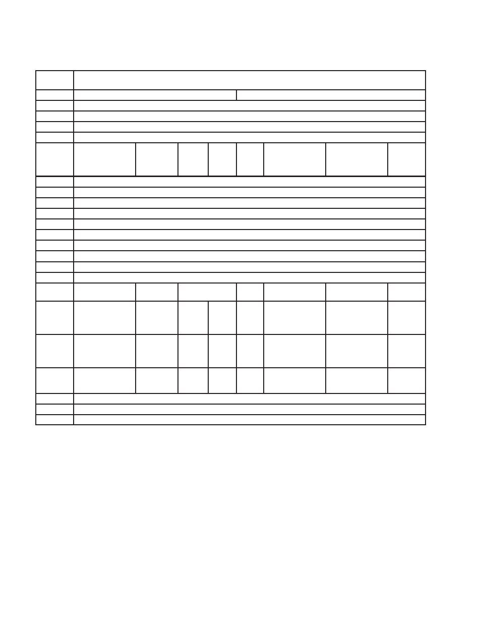
Table 6–2. Serial ROM Map
BYTE
ADDRESS
BYTE DESCRIPTION
00
PCI maximum latency (0h)
PCI_minimum grant (0h)
01
PCI vendor ID
02
PCI vendor ID (msbyte)
03
PCI subsystem ID (lsbyte)
04
PCI subsystem ID
05
[7]
Link_enhancement-
Control.enab_unfair
[6]
HCControl.
ProgramPhy
Enable
[5]
RSVD
[4]
RSVD
[3]
RSVD
[2]
Link_enhancement-
Control.enab_
insert_idle
[1]
Link_enhancement-
Control.enab_accel
[0]
RSVD
06
Mini ROM address
07
GUID high (lsbyte 0)
08
GUID high (byte 1)
09
GUID high (byte 2)
0A
GUID high (msbyte 3)
0B
GUID low (lsbyte 0)
0C
GUID low (byte 1)
0D
GUID low (byte 2)
0E
GUID low (msbyte 3)
0F
Checksum
10
[15]
RSVD
[14]
RSVD
[13–12]
AT threshold
[11]
RSVD
[10]
RSVD
[9]
RSVD
[8]
RSVD
11
[7]
RSVD
[6]
RSVD
[5]
RSVD
[4]
Disable
Target
Abort
[3]
GP2IIC
[2]
Disable SCLK gate
[1]
Disable PCI gate
[0]
Keep PCI
12
[15]
PME D3 Cold
[14]
RSVD
[13]
PME
Support
D2
[12]
RSVD
[11]
RSVD
[10]
D2 support
[9]
RSVD
[8]
RSVD
13
[7]
RSVD
[6]
RSVD
[5]
RSVD
[4]
RSVD
[3]
RSVD
[2]
RSVD
[1]
RSVD
[0]
Global
swap
14
RSVD
15–1E
RSVD
1F
RSVD
- Digital Signal Processor SM320F2812-HT (153 pages)
- MSP430x1xx (440 pages)
- Laser And Motor Drives DRV8811EVM (13 pages)
- TMS320 DSP (88 pages)
- MSP430x11x1 (45 pages)
- TVP5154EVM (55 pages)
- TMS320DM646X DMSOC (64 pages)
- CC2511 (24 pages)
- SN65HVS880 (4 pages)
- TPS650231EVM (14 pages)
- TMS320TCI648x (256 pages)
- TSC2007EVM-PDK (16 pages)
- UCC38500EVM (16 pages)
- TMS320C6000 (62 pages)
- SCAU020 (21 pages)
- TPS40051 (17 pages)
- TNETE2201 (14 pages)
- TMS320C64x DSP (306 pages)
- UCC2891 (21 pages)
- TMS320C3x (757 pages)
- MSP430 (138 pages)
- TMS320C6712D (102 pages)
- MSP430x4xx (512 pages)
- TMS320C6454 (225 pages)
- SPRU938B (48 pages)
- TUSB3210 (22 pages)
- TMS320C6457 (43 pages)
- CC2530ZNP (3 pages)
- TMS320C6455 (50 pages)
- TMS320C6472 (2 pages)
- VLYNQ Port (49 pages)
- TMS380C26 (92 pages)
- MSP-FET430 (95 pages)
- TMS320TCI6486 (160 pages)
- TPS2330 (22 pages)
- DM648 DSP (47 pages)
- TMS320DM36X (134 pages)
- MSC1211 (35 pages)
- SPRAA56 (29 pages)
- DAC7741EVM (28 pages)
- CDCM7005 (34 pages)
- TMS370 (99 pages)
- Adpater (37 pages)
- TMS320C6452 DSP (46 pages)