Figure 9 on, Figure 9 – Nortel Networks M3110 User Manual
Page 47
Attendant consoles
Page 47 of 504
Telephones and Consoles
Description, Installation, and Operation
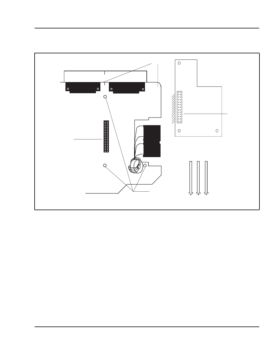
Figure 9
Identifying the correct grid positions on the main PCB and attaching the ASM
5
9
A
B
C
D
Grid marks
Insert Standoffs here
Attendant Supervisory Module
Pin connector
M2250 main PCB (cutaway)
J3 connector
553-AAA0634
See also other documents in the category Nortel Networks Phones:
- T7316 (188 pages)
- T7316E (2 pages)
- T7316 (2 pages)
- i2050 (56 pages)
- NN10300-009 (80 pages)
- NN43112-107 (46 pages)
- NN40050-109 (20 pages)
- 1120E (25 pages)
- 4065R (92 pages)
- Enterprise Edge M7324N (6 pages)
- 2007 (54 pages)
- NN42030-102 (78 pages)
- LDP7004 (1 page)
- MCC 3100 (78 pages)
- LIP-6812 (21 pages)
- 1120 (160 pages)
- CallPilot Desktop Messaging (72 pages)
- Companion MICS-XC (138 pages)
- jAZZ X-6000 (28 pages)
- Meridian M3901 (2 pages)
- Meridian M3902 (146 pages)
- NN42030-101 (108 pages)
- P0609347 02 (8 pages)
- BCM50 (280 pages)
- i2021 Series (77 pages)
- 3100 (72 pages)
- BCM1000 (347 pages)
- C3050 REV2 (42 pages)
- N0035509 (90 pages)
- Enterprise Edge Feature Programming Telephone (170 pages)
- Meridian M3904 (2 pages)
- 6300 (138 pages)
- NN42030-107 (112 pages)
- ATA 2 (16 pages)
- IP Phone 2002 (2 pages)
- 414X (52 pages)
- BST Doorphone (18 pages)
- Regular Telephone (27 pages)
- M2008HF (74 pages)
- Business Communications Manager (BCM) & Norstar Installation (81 pages)
- 1000E (468 pages)
- M2016S (24 pages)
- 2050 (46 pages)
- CallPilot 150 (68 pages)
- BSG12 (2 pages)