Using filters, Filter routing, Filter types – KORG Krome music workstasion 61key User Manual
Page 42
Playing and editing Programs
38
Using Filters
The filters allow you to diminish or emphasize
specified frequency areas of the sound.
The tone of the sound will depend significantly on
the filter settings.
The basic filter settings, including the routing, type,
cutoff frequency, and resonance, are set on the P3–1:
Filter page.
Filter Routing
Each oscillator has two filters, Filter A and Filter B. The
Filter Routing parameter controls whether one or both
of the filters are used, and if both are used, it controls
how they are connected to each other.
The Single routing uses only Filter A as a single 2‐pole,
12dB/octave filter (6dB for Band Pass and Band Reject).
The Serial routing uses both Filter A and Filter B. The
oscillator first goes through Filter A, and then the
output of Filter A is processed through Filter B.
Parallel also uses both Filter A and Filter B. The
oscillator feeds both filters directly (and allow
independent settings for each), and the outputs of the
two filters are then summed together.
The 24dB(4Pole) routing merges both filters to create a
single 4‐pole, 24dB/octave filter (12dB for Band Pass
and Band Reject). In comparison to Single, this option
produces a sharper roll‐off of frequencies beyond the
cutoff frequency, as well as a slightly more delicate
resonance. Many classic analog synths used this type
of filter.
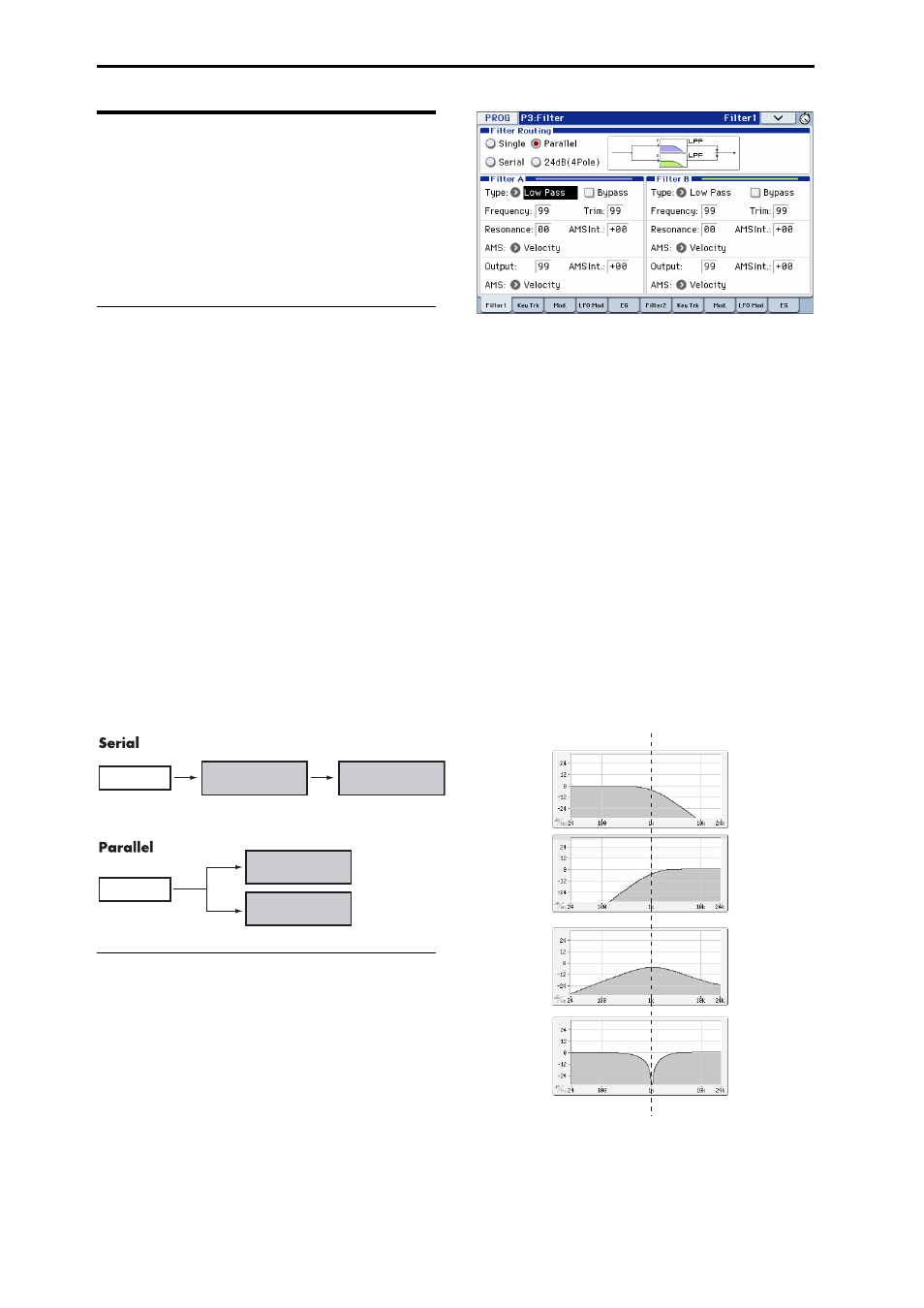
Serial and Parallel Routing
Filter Types
This selects the parts of the sound that will be affected
by the filter, as described below. With the Serial and
Parallel routings, you can independently set the types
for Filter A and Filter B.
The filters will produce very different results
depending on the selected filter type.
Low Pass: This cuts out the parts of the sound that are
higher than the cutoff frequency. Low Pass is the most
common type of filter, and is used to make bright
timbres sound darker.
High Pass: This cuts out the parts of the sound that are
lower than the cutoff frequency. You can use this to
make timbres sound thinner or more buzzy.
Band Pass: This cuts out all parts of the sound, both
highs and lows, except for the region around the cutoff
frequency. Since this filter cuts out both high and low
frequencies, its effect can change dramatically
depending on the cutoff setting and the oscillator’s
multisample.
With low resonance settings, you can use the Band
Pass filter to create telephone or vintage phonograph
sounds. With higher resonance settings, it can create
buzzy or nasal timbres.
Band Reject: This filter type–also called a notch filter–
cuts only the parts of the sound directly around the
cutoff frequency. Try modulating the cutoff with an
LFO to create phaser‐like effects.
Filter Types and Cutoff Frequency
Filter A (Low Pass)
Oscillator
Oscillator
Filter B (High Pass)
Filter A (Low Pass)
Filter B (High Pass)
Low Pass
High Pass
Band Pass
Band Reject
Cutoff Frequency