As-interface slaves, I/o modules for operation in the field, Digital i/o modules ip67 - k45 – Siemens ISI EN 50295 User Manual
Page 58
Siemens IK PI · 2004
6/58
AS-Interface Slaves
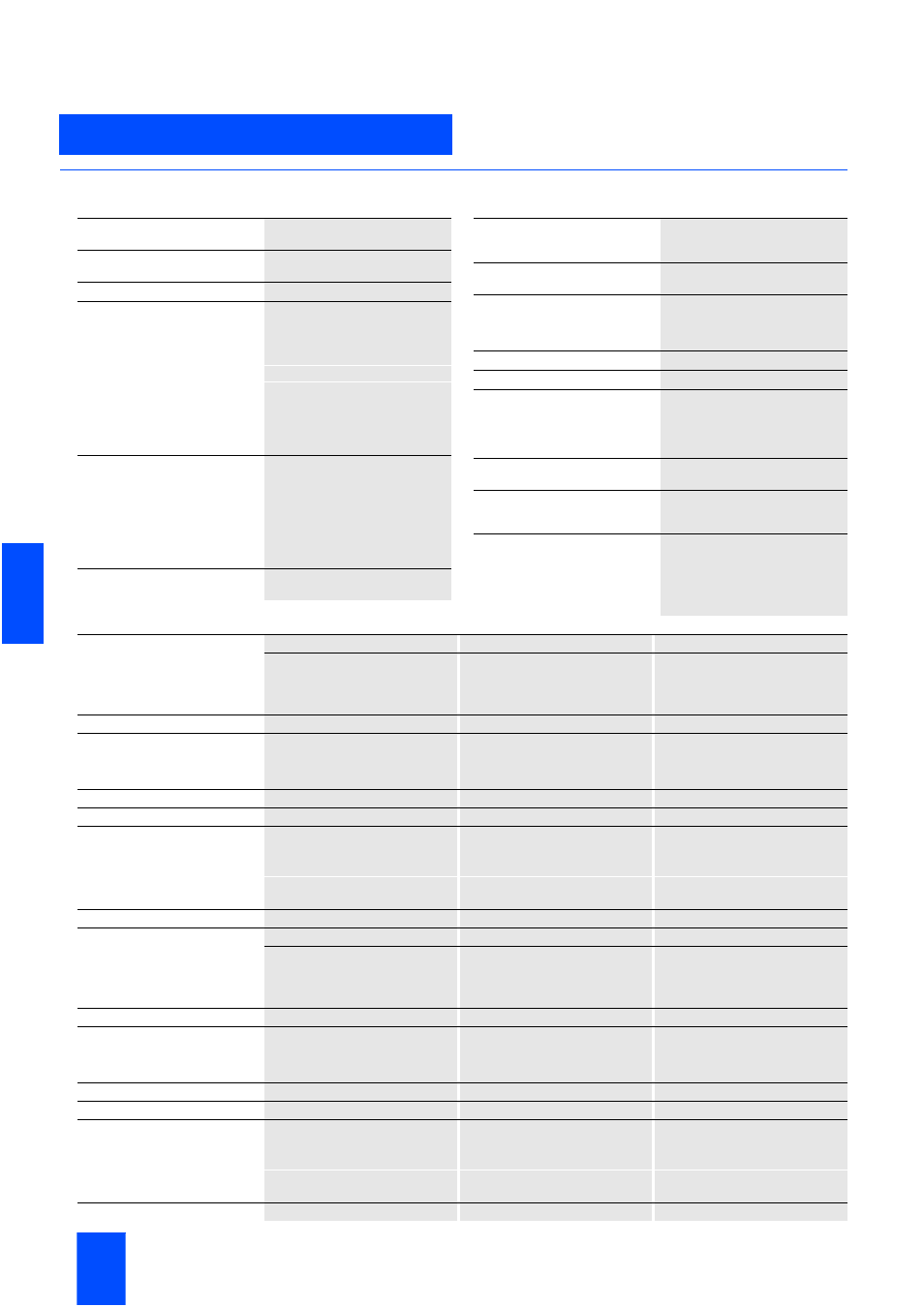
Digital I/O modules IP67 - K45
I/O modules for operation in the field
6
■
Technical specifications
Technical specifications common to all IP67 – K45 digital I/O modules
1) for 3RK2 400-1BQ20-0AA3 U
min
= 16.5 V
Operational voltage in accordance
with AS-Interface specification in V
26.5 to 31.6
Polarity reversal protection U AS-
Interface
Built-in
Input connection
PNP
Inputs
• Sensor supply via AS-Interface
Short-circuit and overload with-
stand capability
• Sensors
2- and 3-wire
• Voltage range in V
20 to 30
• Current carrying capacity
for all inputs
(T
u
£ 40 °C) in mA
200
• Switching level High in V
³ 10
• Input current Low/High in mA
£ 1.5 / ³ 6
Outputs
• Type of output
Electronics
• Short-circuit protection
Built-in
• Inductive interference protection
(free-wheeling diode)
Built-in
• External 24 V DC supply voltage
Over black AS-Interface flat cable
• Watchdog
Built-in
AS-Interface certificate
Available (or under application
in the case of new products)
Approvals
UL, CSA, marine certification
(or under application in the case
of new products)
Degree of protection
IP67 (IP65 for M8 snap-on con-
nection)
Ground connection
Through PIN5 of the M12 socket
and outgoing through a 2.8 mm
tab connector (no earth connec-
tion for M8 sockets)
Ambient temperature in °C
-25 to +85
Storage temperature in °C
-40 to +85
Status indications
• I/O display
Yellow LED
• Display U
Aux
Green LED
• AS-Interface/diagnostics display
Dual LED, green/red
Connection
Using mounting plate for K45
compact module
Note 1
All K45 compact modules are
supplied with high-grade steel
screws/sockets
Note 2
To supply the output circuit, an
external supplementary supply
(AUX POWER) of 20 to 30 V DC is
necessary. The supplementary
supply must comply with VDE
0106 (PELV), Safety Class III.
4 inputs
4 inputs
4 inputs
Standard slaves
Standard slaves
Standard slave
Standard assignment
Standard assignment
Standard assignment
M12
M8 screw connection
M8 screw connection
3RK1 200–0CQ20–0AA3
3RK1 200–0CT20–0AA3
3RK1 200–0CU20–0AA3
Total current input in mA
£ 270
£ 270
£ 270
Socket assignment, inputs
PIN1 = Sensor supply L+
PIN3 = Sensor supply L-
PIN4 + 2 = Data input
PIN5 = Ground connection
PIN1 = Sensor supply L+
PIN3 = Sensor supply L-
PIN4 = Data input
PIN1 = Sensor supply L+
PIN3 = Sensor supply L-
PIN4 = Data input
I/O configuration
0
0
0
ID/ID2 code
0/F
0/F
0/F
Assignment of data bits
• Socket 1
PIN4/2 = IN1(D0)
PIN4 = IN1(D0)
PIN4 = IN1(D0)
• Socket 2
PIN4/2 = IN2(D1)
PIN4 = IN2(D1)
PIN4 = IN2(D1)
• Socket 3
PIN4/2 = IN3(D2)
PIN4 = IN3(D2)
PIN4 = IN3(D2)
• Socket 4
PIN4/2 = IN4(D3)
PIN4 = IN4(D3)
PIN4 = IN4(D3)
Number of I/O sockets
4
4
4
4 inputs
4 inputs
4 inputs
A/B slave
A/B slaves
A/B slaves
Standard assignment
Standard assignment
Standard assignment
M12
M8 screw connection
M8 screw connection
3RK2 200–0CQ20–0AA3
3RK2 200–0CT20–0AA3
3RK2 200–0CU20–0AA3
Total current input in mA
£ 270
£ 270
£ 270
Socket assignment, inputs
PIN1 = Sensor supply L+
PIN3 = Sensor supply L-
PIN4 + 2 = Data input
PIN5 = Ground connection
PIN1 = Sensor supply L+
PIN3 = Sensor supply L-
PIN4 = Data input
PIN1 = Sensor supply L+
PIN3 = Sensor supply L-
PIN4 = Data input
I/O configuration
0
0
0
ID/ID2 code
A/0
A/0
A/0
Assignment of data bits
• Socket 1
PIN4/2 = IN1(D0)
PIN4 = IN1(D0)
PIN4 = IN1(D0)
• Socket 2
PIN4/2 = IN2(D1)
PIN4 = IN2(D1)
PIN4 = IN2(D1)
• Socket 3
PIN4/2 = IN3(D2)
PIN4 = IN3(D2)
PIN4 = IN3(D2)
• Socket 4
PIN4/2 = IN4(D3)
PIN4 = IN4(D3)
PIN4 = IN4(D3)
Number of I/O sockets
4
4
4