Usb host port and ethernet port, Ethernet port, Additional oem interface signals – Silex technology Embedded Intelligent Module SX-560 User Manual
Page 22: Serial peripheral interface
Page 16
silex
Installing the Evaluation Daughtercard
Part Number 140-00192-100
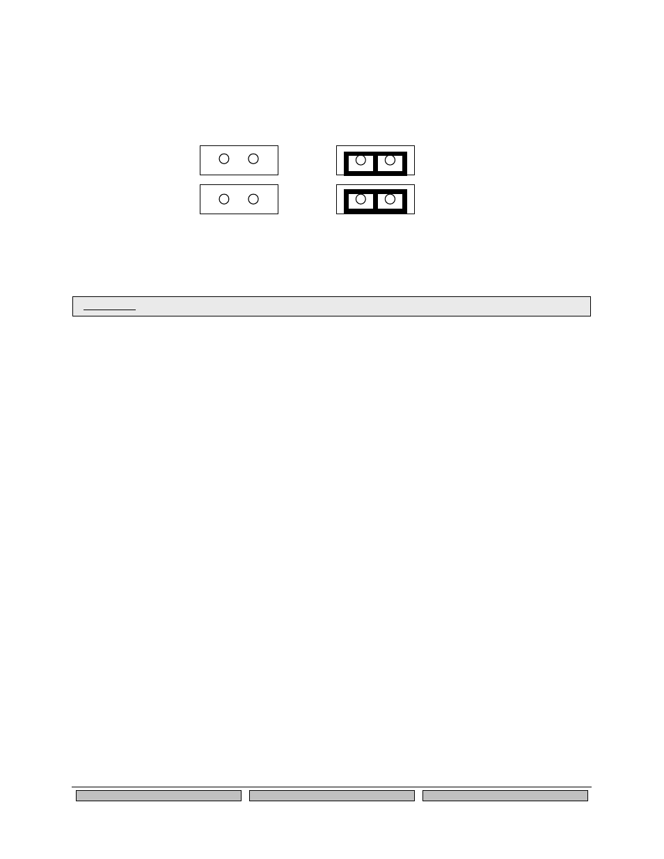
USB Host Port and Ethernet Port
The USB V1.1 host port, located on J1, can be used to connect standard Full Speed (12Mbps) or Low
Speed (1.5Mbps) USB devices. High Speed (480Mbps) is not supported.
The USB port is disabled by default. To enable it, remove the jumpers on headers JP4 and JP5 as
shown below.
JP4
JP5
USB Enabled
Ethernet Enabled
No jumpers installed
2 Jumpers installed
(default position)
Figure 7 USB/Ethernet Jumper Settings
Ethernet Port
The Ethernet port, located on J2, can be used for configuring and testing the SX-560. Ethernet provides
an easier way to do the initial setup and configuration of the SX-560, because you do not have to worry
about wireless security configuration parameters. Operation of the SX-560 through this port is identical to
wireless operation, except that wireless security is not supported. Ethernet is enabled by default (see
previous section for information on jumper settings).
Note that because the Ethernet port is connected through the USB host port, it cannot be used at the
same time as the USB port. Also, when the Ethernet port is used, the 802.11a/b/g wireless port is
disabled.
Additional OEM Interface Signals
The output LED signals ORLED-, GRLED- and YELED- represent the state of the LEDs on the module.
Logic 0 indicates the LED is on, and Logic 1 indicates the LED is off. Buffers are recommended if LEDs
are to be driven on the end-user side.
The SWITCH signal is connected to a momentary pushbutton switch (Test Button) on the Evaluation
Daughtercard and is in the normally open position. Depressing the switch causes a short to ground. A
4.7 K-ohm pull-up resistor to +3.3 VDC is connected. The module’s processor monitors this signal. The
end-user can drive or use open-collector to this signal to either logic level or can monitor this signal as an
input. The Test Button is normally used either to send configuration information to a printer (button
momentarily pressed) or to reset the SX-560 to its default configuration (button held down for more than 5
seconds).
Serial Peripheral Interface
The four SPI signals are accessible using the 26-pin I/O header JP3. The SPI MOSI, SPI MISO, and SPI
Clock signals are routed to both the JP3 header and an on-board temperature sensor. The temperature
sensor can be disabled by removing the jumper from the TSPICS signal on JP7 as described in the GPIO
Special Functions section above.
IMPORTANT: Do not plug a USB device into the USB port if the Ethernet port is enabled.