Silex technology Embedded Intelligent Module SX-560 User Manual
Page 20
Page 14
silex
Installing the Evaluation Daughtercard
Part Number 140-00192-100
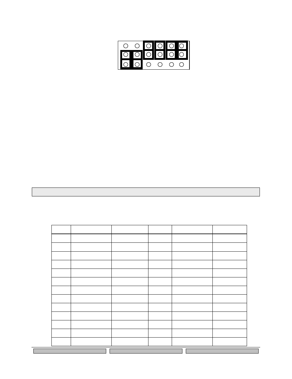
Figure 6 GPIO Special Functions Jumpers (Example Configuration)
The GPIOs are accessed via header JP3 as described in the next section. You can set and read the
GPIO state, and set Email alerts and SNMP traps based on the GPIO state as described in Chapter 6 of
this manual.
26-Pin I/O Header
The I/O Header, located at JP3, is a 26-pin interface for connecting to the SX-560 GPIO and SPI
interfaces. It also provides a direct way of connecting to the SX-560 console interface using 3.3V logic
levels rather than the DB-9 RS-232 connector.
The GPIOs, located on JP3, can be used for controlling or monitoring OEM functions. External pull-ups
are recommended for customization.
Table 9 26-Pin I/O Header
Pin
Signal
Selectable
Pin
Signal
Selectable
1
GPIO_1
2
GPIO_0
3
GPIO_2
4
3.3V
5
GND
6
HGPIO_3
Via JP7
7
HGPIO_5
Via JP7
8
HGPIO_4
Via JP7
9
HGPIO_7
Via JP7
10
HGPIO_6
Via JP7
11
GPIO_9
12
HGPIO_8
Via JP7
13
3.3V
14
GPIO_10
15
SPI CLK
16
GND
17
SPI SLVCS-
18
SPI MOSI
19
TXD2
20
SPI MISO
21
GND
22
RXD2
23
IIC SCL
24
3.3V
25
IIC SDA
26
RESET-
G
PI
O
3
G
PI
O
4
G
PI
O
5
G
PI
P
6
G
PI
O
7
G
PI
O
8
T
SPI
C
S
D
T
R
0
D
SR
0
D
C
D
0
G
R
N
YEL
JP7
JP8
JP9
NOTE: GPIO_10 is fixed as a switch input (Test Button) and GPIO_9 is fixed as an LED output (power on/off).