Monitoring module status, Oem interface – Silex technology Embedded Intelligent Module SX-560 User Manual
Page 15
Installing the Evaluation Daughtercard
Silex
Page 9
Part Number 140-00192-100
Monitoring Module Status
You can monitor the module status using the yellow, green and orange LED status indicators on the
Evaluation Daughtercard. Table 2 defines the default functions of the LED status indicators.
Table 2 Status Monitors
Function
State
Status
On
The module is receiving power
Off
The module is not receiving power
Power
Orange (D8)
Blinking
Firmware update is in progress (Important: Do not
power off the module during the update process)
Network Status
Yellow (D9)
Yellow On
Wireless connection established
OEM Interface
The OEM interface is a 40-pin header (JP2) that is used to connect the SX-560 module to the SX-560-6900
Evaluation Daughtercard. It will also serve as the primary means of communications between the SX-560 and
your OEM device (refer to Chapter 5 for information on using this header to connect with your device).
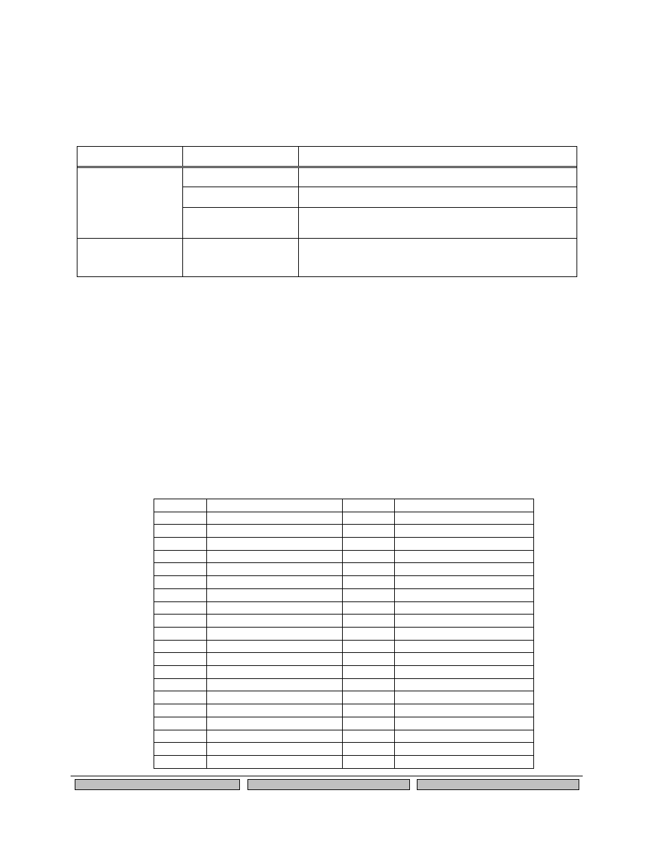
Table 3 shows the OEM interface pinout for the Evaluation Daughtercard. Table 4 shows the OEM
interface signal descriptions. Please note that the OEM interface signals are not directly accessible from
the OEM header when the Evaluation Daughtercard is used. Rather, these signals are available through
convenient connectors on the Evaluation Daughtercard, such as the 26-pin I/O Header and the 9-pin
serial connectors. These connectors are described later in this chapter.
All input and output signals, except the differential signals, are 0 to 3.3 V logic signals.
Table 3 OEM Interface Pinout
PIN
SIGNAL
PIN
SIGNAL
1
RESETI-
2
GPIO_0
3
GPIO_1
4
GPIO_2
5
GROUND
6
+3.3VDC
7
GPIO_3
8
GPIO_4
9
GPIO_5
10
GPIO_6
11
GPIO_7
12
GPIO_8
13
GPIO_9
14
TXD0
15
GPIO_10
16
CTS0-
17
GROUND
18
+3.3VDC
19
USB+
20
RTS0-
21
USB-
22
RXD0
23
+3.3VDC
24
GROUND
25
SPI_CS-
26
TXD1
27
SPI_CLK
28
CTS1-
29
GROUND
30
+3.3VDC
31
SPI_MOSI
32
RTS1-
33
SPI_MISO
34
RXD1
35
+3.3VDC
36
GROUND
37
IIC_SDC
38
TXD2
39
IIC_SDA
40
RXD2