Silex technology Embedded Intelligent Module SX-560 User Manual
Page 19
Installing the Evaluation Daughtercard
Silex
Page 13
Part Number 140-00192-100
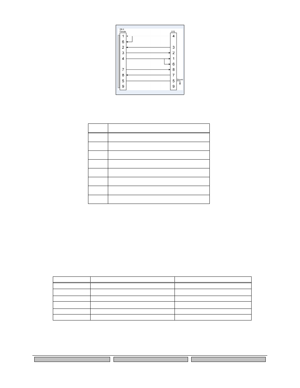
Figure 5 RS-232 Cable Pinouts
Table 7 RS-232 Cable Pinout Description
Pin
Description
1
DCD (Data Carrier Detect) Input*
6
DSR (Data Set Ready) Input*
2
RxD (Receive Data) Input
3
TxD (Transmit Data) Output
4
DTR (Data Terminal Ready) Output*
7
RTS (Request To Send) Output*
8
CTS (Clear To Send) Input*
5
Ground
*Note: Serial Port 1 (J3) supports all signals. Serial Port 2 (J4) supports RxD, TxD, RTS, and CTS.
Serial Port 3 (J5; dedicated console port) supports RxD and TxD only.
Using the GPIO Special Functions
Six of the General Purpose I/Os (GPIOs) can be configured for either user-defined operations or for GPIO
for special functions. These special functions are summarized in the following table:
Table 8 GPIO Special Functions
Special Function (default setting)
Description
GPIO_3
TSPICS
Enable SPI temperature sensor
GPIO_4
DTR0
Serial Port 1 DTR modem signal
GPIO_5
DSR0
Serial Port 1 DSR modem signal
GPIO_6
DCD0
Serial Port 1 DCD modem signal
GPIO_7
GRN
Green status LED (D10)
GPIO_8
YEL
Yellow status LED (D9)
The mode of operation for each of the GPIOs can be set by installing jumpers between headers JP7 and
JP8 for GPIO operation, or between headers JP8 and JP9 for special function operation (all of the special
functions are enabled by default). For example, in the follow diagram, GPIO_3 is enabled for SPI
temperature sensor, while GPIO_4 is enabled as the DTR signal (DTR0) for Serial Port 1. The GPIO_5
through GPIO_8 are used as normal GPIOs in this example.