Control and connection panel, 1 control and connection panel, Control and connection panel fc switch blade – FUJITSU PRIMERGY BX600 S2 User Manual
Page 106: The led might also blink while testing, Primergy bx600 s2 basic unit
106
PRIMERGY BX600 S2 Basic Unit
Control and Connection Panel
FC Switch Blade
©
c
o
g
n
it
as
.
Ge
s
e
lls
c
h
ft
f
ü
r T
e
c
h
n
ik
-Do
k
u
m
e
nt
at
io
n
m
b
H
2
007
P
fad:
H:
\w
in
dows
\_p
roj
e
k
te\
B
x
z
\B
e
tr
ie
b
s
a
n
le
it
un
g\
V
e
rs
ion_
M
a
e
rz
-2
007
\A
rc
h
iv
\B
X
6
0
0
S
2
_
en\
bl
ad
e-u
s
.k
0
9
10.1
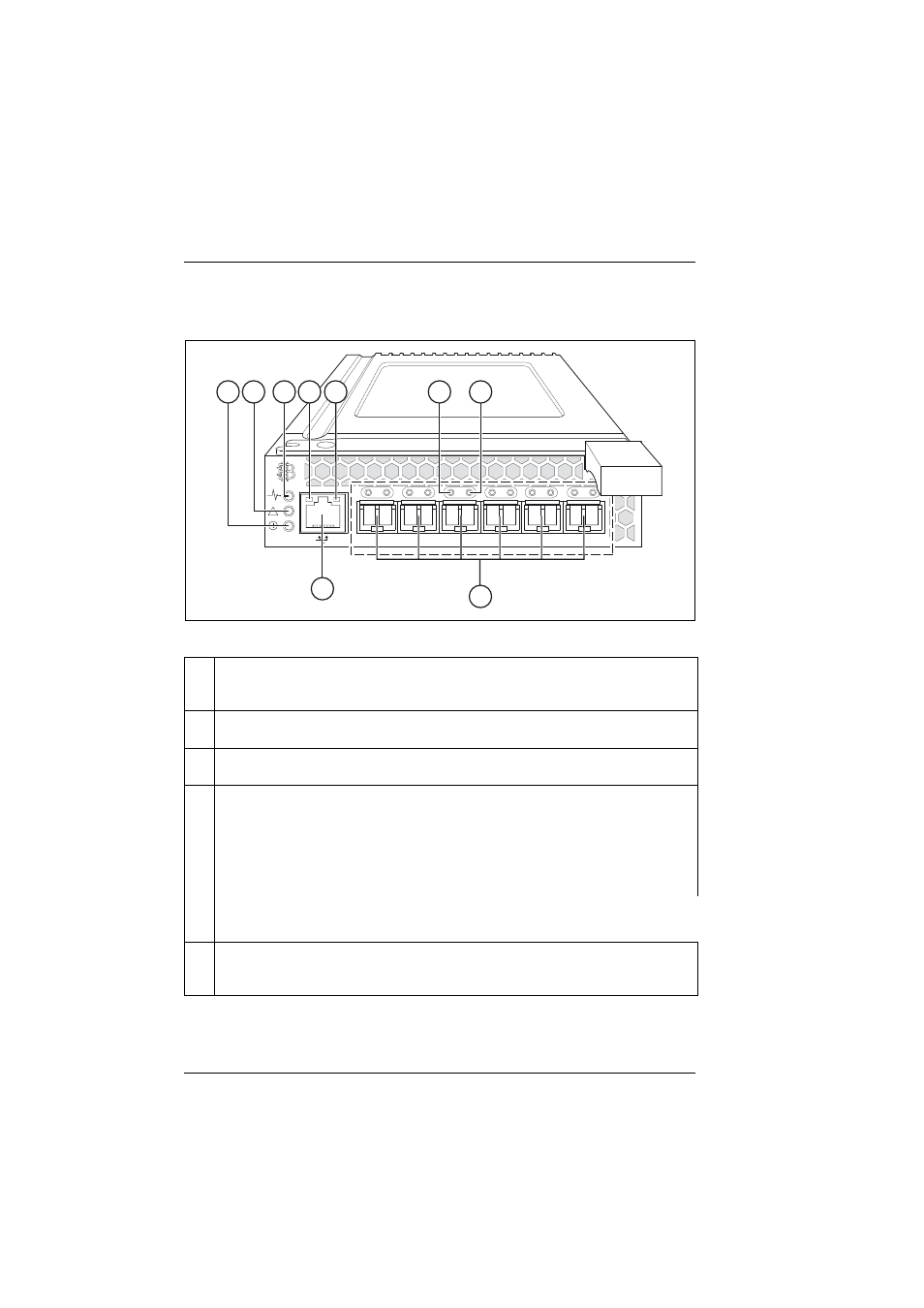
Control and Connection Panel
Figure 59: Control and Connection Panel of the FC switch blade
1
External FC connection (6x)
socket for LWL or SWL FC SFP module (see
section “Fibre Channel SFP module” on
).
2
RJ45 LAN connection
with two integrated status LEDs (see items 6 and 7)
3
FC switch blade voltage status display (green LED)
lights up when the base unit is switched on (12 V input voltage present).
4
FC switch blade status display (2-color LED)
Dark:
FC switch blade is not operating
Lights green:
FC switch blade is operating
Lights amber:
Boot phase; one or more ports are off-line
Blinks amber/green:
Warning: a fault has occurred.
I
The LED might also blink while testing.
5
Management blade display (2-color LED)
Lights up when the FC switch blade is being controlled directly via the management
blade user interface.
10
11
12
13
14
15
!
1
2
3
4
5
6
7
8
9