Uguy, Every cabinet contains one uguy. refer to, The uguy consists of two main components – HP A9834-9001B User Manual
Page 31: Figure12 uguy, Clu functionality, Figure 1-2. uguy
Chapter 1
Overview
Utilities Subsystem
31
- Supports USB for keyboard and mouse at boot
- Supports VGA during boot
- Enables global shared memory (GSM)
- Supports PCI 2.3, PCI-X 1.0, and PCI-X 2.0
UGUY
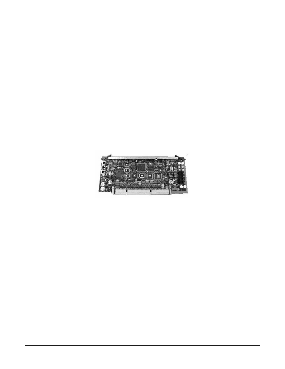
Every cabinet contains one UGUY. Refer to Figure 1-2. The UGUY plugs into the HUCB. It is not hot
swappable. Its MP microprocessor controls power monitor functions, executing the Power Monitor 3 (PM3)
firmware and the cabinet-level utility (CLU) firmware.
The UGUY consists of two main components:
- CLU
- PM3
Figure 1-2
UGUY
CLU Functionality
The CLU is responsible for collecting and reporting the configuration information for itself, main backplane,
I/O backplanes, and the SUB/HUB. Each of these boards is furnished with a configuration EEPROM
containing FRU IDs, revision information, and, for the main backplane and I/O backplanes, maximum power
requirements for that entity in its fully configured, fully loaded state. The power requirement information is
sent to the PM3 automatically when HKP is applied or when a new entity is plugged in. The configuration
information is sent to the SUB in response to a get_config command.
The CLU gathers the following information over its five I2C buses:
- Board revision information is contained in the board's configuration EEPROM for the UGUY board (UGUY),
the SBCH board (SBCH), the main backplane, the main backplane power boards (HBPB), the I/O backplane
(HIOB), and the I/O backplane power boards (IOPB).
- Power requirements from the configuration EEPROM for the main backplane (HLSB or HRSB), the I/O
backplanes (HIOB). This information is sent to the PM3 processor (via USB) so that it can calculate cabinet
power requirements.
- Power control and status interface. Another function of the UGUY is to use the power_ good signals to drive
power on
- Reset control which includes a reset for each I/O backplane, a main backplane cabinet reset, TRST - JTAG
reset for all JTAG scan chains in entire cabinet, a system clock control margin control