Figure327 a 5-wire connector, Pdca:installation;installation:pdca, Pdca:wiring configurations – HP A9834-9001B User Manual
Page 105: Use the following procedure to install the pdca, Figure 3-27. a 5-wire connector
Chapter 3
Installing the System
Setting Up the System
105
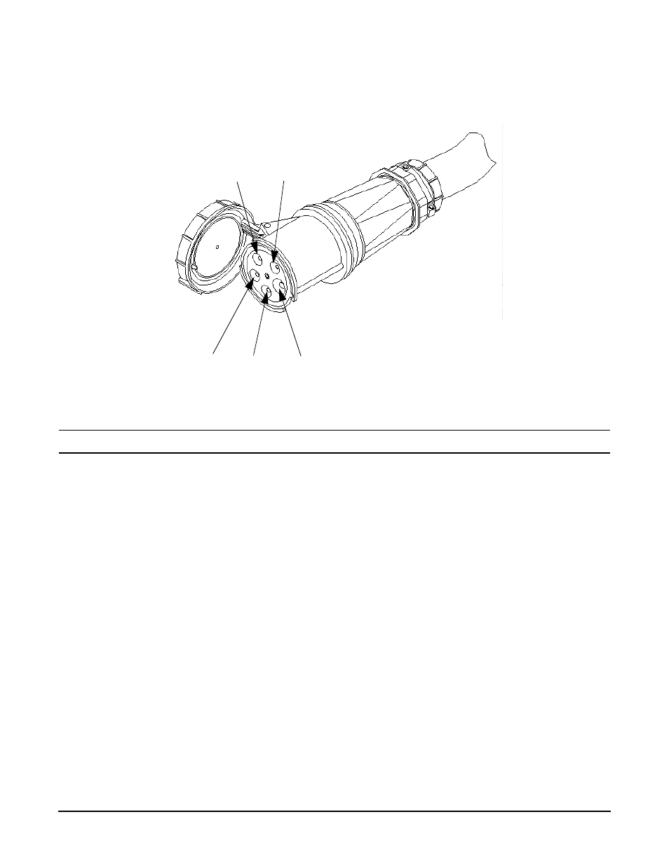
Figure 3-27
A 5-Wire Connector
Use the following procedure to install the PDCA:
WARNING
Make sure the circuit breaker on the PDCA is OFF.
Step 1. Remove the rear PDCA bezel by removing the four retaining screws.
Step 2. Run the power cord down through the appropriate opening in the floor tile.
Step 3. Insert the PDCA into its slot and secure with four screws (Figure 3-28 on page 106).
L1
PE
L3
N
L2
This manual is related to the following products:
See also other documents in the category HP Computers:
- UX B6941-90001 (548 pages)
- A3661B (95 pages)
- C100/110 (252 pages)
- L1702 (45 pages)
- 576X-B (1 page)
- rx5670 (13 pages)
- ProLiant PC2-6400 (38 pages)
- PC (120 pages)
- S3240 (2 pages)
- LC 2000R (194 pages)
- GS80 (41 pages)
- COMPAQ DX2710 MT (107 pages)
- TOUCHSMART 9100 (62 pages)
- BC1500 (13 pages)
- Proliant DL580 (48 pages)
- Proliant DL580 (53 pages)
- DX2200 (31 pages)
- ProLiant Server Blade BL460c (31 pages)
- P6000 (105 pages)
- d530 Series (2 pages)
- dc5700 (216 pages)
- RX7620-16 (43 pages)
- ProLiant ML370 G5 (46 pages)
- PROLIANT ML350 G6 (54 pages)
- BL35P (22 pages)
- COMPAQ DC5750 (214 pages)
- Agent-Desktop-Laptop Computer (23 pages)
- DL380 G7 (126 pages)
- xw8600 (73 pages)
- Pavilion A6140 (2 pages)
- Z800 (55 pages)
- 8080 ELITE BUSINESS (284 pages)
- Vectra XE320 (82 pages)
- Vectra XE320 (32 pages)
- VECTRA VL800 (72 pages)
- AA-RTDRB-TE (146 pages)
- BL465C (66 pages)
- DM4 (113 pages)
- PROLIANT 580554-001 (87 pages)
- ProLiant ML330 (34 pages)
- ProLiant ML330 (44 pages)
- PROLIANT BL465C G7 (30 pages)
- LH 3r (23 pages)
- Compaq dc7900 (3 pages)
- T5000 (41 pages)