Preliminar y, Operation, cont’d – Extron electronic VGA MATRIX SWITCHERS MVX PLUS 128 User Manual
Page 28
Operation, cont’d
MVX Plus 128 VGA Matrix Switchers • Operation
3-6
PRELIMINAR
Y
h
Audio button — The Audio button has two primary functions (•) and three
secondary (
❏) functions
•
Selects and deselects audio for a confi guration that is being created or
viewed.
•
Lights to indicate that audio is available for confi guration or viewing.
❏ Selects
the
Audio mode, in which you can adjust the input audio level and
the output audio volume. See Viewing and adjusting the input audio level
on page 3-29 and Viewing and adjusting the output volume on page 3-33.
❏ With the RGBHV button, toggles the front panel lock on or off.
See Locking out the front panel (Executive mode) on page 3-38.
❏ With the RGBHV button, commands the front panel system reset.
See Performing a system reset from the front panel on page 3-38.
❏ Select the RS-422 protocol for the RS-232/RS-422 port in Serial Port
Confi guration mode. See Selecting the RS-232/RS-422 protocol and baud rate
on page 3-40.
❏ Indicate that the RS-232/RS-422 port is set to the RS-422 protocol in Serial
Port Confi guration mode. See Selecting the RS-232/RS-422 protocol and baud
rate on page 3-40.
Button icons
The numbered translucent covers on the input and output pushbuttons can be
removed and replaced to insert labels behind the covers.
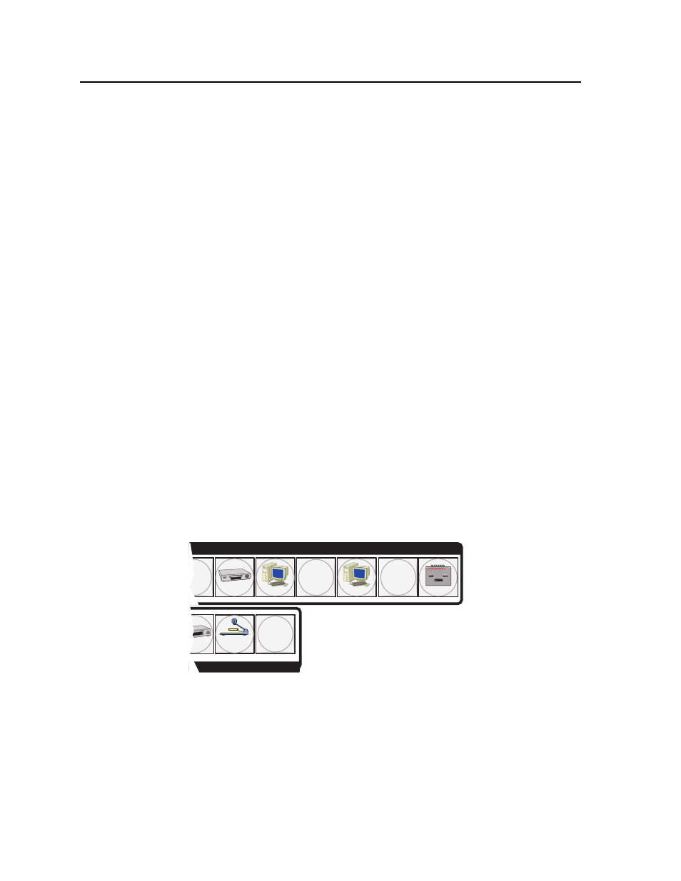
Input and output labels can be created easily with Extron’s Button-Label Generator
software, which ships with every Extron matrix switcher. Each input and output
can be labeled with names, alphanumeric characters, or even color bitmaps for
easy and intuitive input and output selection (fi gure 3-2). See chapter 5, Matrix
Software, for details on using the labeling software. See Appendix B, Specifi cations,
Part Numbers, and Accessories, for blank labels and a procedure for removing and
replacing the translucent covers.
DVD
VCR
Computer
Computer
Document
Camera
VTG 200
6
9
11
8
INPUTS
Figure 3-2 — Sample button icons