Preliminar y, Introduction, cont’d, Features – Extron electronic VGA MATRIX SWITCHERS MVX PLUS 128 User Manual
Page 14
Introduction, cont’d
MVX Plus 128 VGA Matrix Switchers • Introduction
1-4
PRELIMINAR
Y
Features
Video —
The switchers input and output RGBHV or RGBS (VGA) video on
15-pin HD connectors. They can also switch RGsB, RsGsBs, component/
HDTV, S-video, or composite video.
Bandwidth —
The MVX switchers provide a minimum of 300 MHz (-3 dB) video
bandwidth, fully loaded.
Audio inputs —
Input and output stereo audio, balanced or unbalanced, is
provided on 3.5 mm, 5-pole captive screw terminals.
Audio input gain/attenuation —
Individual input audio levels can be adjusted so
there are no noticeable volume differences between sources. Users can set the
input level of audio gain or attenuation (-18 dB to +24 dB) via the Ethernet
link, RS-232/RS-422 link, or the front panel.
Audio output volume
— The audio volume of each output can be displayed and
adjusted through a range of full output to completely silent, from the front
panel or under RS-232/RS-422 or Ethernet control.
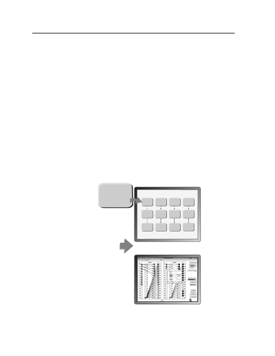
Digital Sync Validation Processing (DSVP
™) — In critical environments or
unmanned, remote locations, it may be vital to know that sources are active
and switching. Extron’s DSVP confi rms that input sources are active by
scanning all sync inputs for active signals. DSVP provides instantaneous
frequency feedback for composite sync or separate horizontal and vertical
sync signals via the switcher’s RS-232/RS-422 or Ethernet port. The
frequency information can be displayed on any control system or in a
Windows
®
-based control program on a local-area network (LAN) or Internet
(IP) connection (fi gure 1-2).
OR
Input Horz. Vert.
01 31.50 60.00
02 31.50 60.00
03 31.50 60.00
04 48.01 67.50
05 48.01 67.50
06 48.01 67.50
07 48.01 67.50
08 61.55 72.00
09 61.55 72.00
10 61.55 72.00
11 61.55 72.00
12 61.55 72.00
Sample control system panel
Windows-based control program
MATRIX INPUT STATUS
Input # 01
Signal: PRESENT
Sync Type: H&V
Vertical Freq.: 60 Hz
Horz Freq.: 31.5 kHz
Input # 02
Signal: PRESENT
Sync Type: H&V
Vertical Freq.: 60 Hz
Horz Freq.: 31.5 kHz
Input # 03
Signal: PRESENT
Sync Type: H&V
Vertical Freq.: 60 Hz
Horz Freq.: 31.5 kHz
Input # 04
Signal: PRESENT
Sync Type: H&V
Vertical Freq.: 60 Hz
Horz Freq.: 31.5 kHz
Input # 05
Signal: PRESENT
Sync Type: H&V
Vertical Freq.: 60 Hz
Horz Freq.: 31.5 kHz
Input # 06
Signal: PRESENT
Sync Type: H&V
Vertical Freq.: 60 Hz
Horz Freq.: 31.5 kHz
Input # 07
Signal: PRESENT
Sync Type: H&V
Vertical Freq.: 60 Hz
Horz Freq.: 31.5 kHz
Input # 08
Signal: PRESENT
Sync Type: H&V
Vertical Freq.: 60 Hz
Horz Freq.: 31.5 kHz
Input # 09
Signal: PRESENT
Sync Type: H&V
Vertical Freq.: 60 Hz
Horz Freq.: 31.5 kHz
Input # 10
Signal: PRESENT
Sync Type: H&V
Vertical Freq.: 60 Hz
Horz Freq.: 31.5 kHz
Input # 11
Signal: PRESENT
Sync Type: H&V
Vertical Freq.: 60 Hz
Horz Freq.: 31.5 kHz
Input # 12
Signal: PRESENT
Sync Type: H&V
Vertical Freq.: 60 Hz
Horz Freq.: 31.5 kHz
Input # 01
Signal: PRESENT
Sync Type: H&V
Vertical Freq.: 60 Hz
Horz Freq.: 31.5 kHz
Figure 1-2 — DSVP data display