Preliminar y, Operation, Front panel controls and indicators – Extron electronic VGA MATRIX SWITCHERS MVX PLUS 128 User Manual
Page 24: Defi nitions
MVX Plus 128 VGA Matrix Switchers • Operation
3-2
Operation
PRELIMINAR
Y
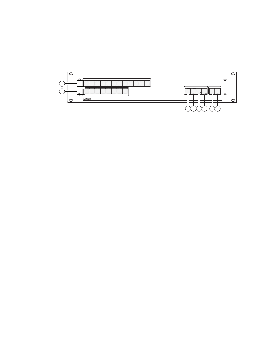
Front Panel Controls and Indicators
The front panel controls (fi gure 3-1) are grouped into two sets. The input and
output buttons are grouped on the left side of the control panel. The control
buttons and video/audio (I/O) selection buttons are grouped on the right side of
the panel.
MVX PLUS SERIES
AUDIO
VIDEO
I/O
CONTROL
ENTER
PRESET
VIEW
ESC
INPUTS
1
2
3 4
5 6
7 8
9 10 11 12
OUTPUTS
1
2 3 4 5
6 7
8
VGA MATRIX SWITCHER
WITH
IP LINK™
8
6
5
4
3
7
1
2
Figure 3-1 — Front panel, MVX Plus 128 A
The large, illuminated push buttons can be labeled with text and/or graphics.
The buttons can be set to provide amber background illumination all the time or
the background illumination can be turned off (see Background illumination, on
page 3-39. The buttons blink or are lit at full intensity (depending on the operation)
when selected.
Defi nitions
The following terms, which apply to Extron matrix switchers, are used throughout
this manual:
Tie
—
An input-to-output connection.
Set of ties —
An input tied to two or more outputs. (An output can never be tied
to more than one input.)
Confi guration —
One or more ties or one or more sets of ties.
Current
confi guration —
The confi guration that is currently active in the
switcher (also called confi guration 0)
Global memory preset —
A confi guration that has been stored. Up to 32 global
memory presets
can be stored in memory. Preset locations are assigned to the
input buttons and output buttons. Up to 20 presets can be selected from the
front panel for either saving or retrieving. When a preset is retrieved from
memory, it becomes the current confi guration. All models have 32 presets;
preset numbers higher than 21, too high to be available from the front panel
are still accessible under RS-232/RS-422 or Ethernet control.
Room
—
A subset of outputs that are logically related to each other, as
determined by the operator. The switchers support up to 10 rooms, each of
which can consist of from 1 to 16 outputs.
Room memory preset —
A confi guration consisting of outputs in a single room
that has been stored. When a room preset is retrieved from memory, it
becomes the current confi guration.