Preliminar y, Installation, Mounting the switcher – Extron electronic VGA MATRIX SWITCHERS MVX PLUS 128 User Manual
Page 18: Cabling and rear panel views, Video connections
MVX Plus 128 VGA Matrix Switchers • Installation
2-2
Installation
PRELIMINAR
Y
Mounting the Switcher
The matrix switchers are housed in rack-mountable, 2U high metal enclosures with
mounting fl anges for standard 19” racks. If desired, rack mount the switcher as
follows:
1
.
Insert the switcher into the rack, aligning the holes in the mounting bracket
with those in the rack.
2
.
Secure the switcher to the rack using the supplied bolts.
Cabling and Rear Panel Views
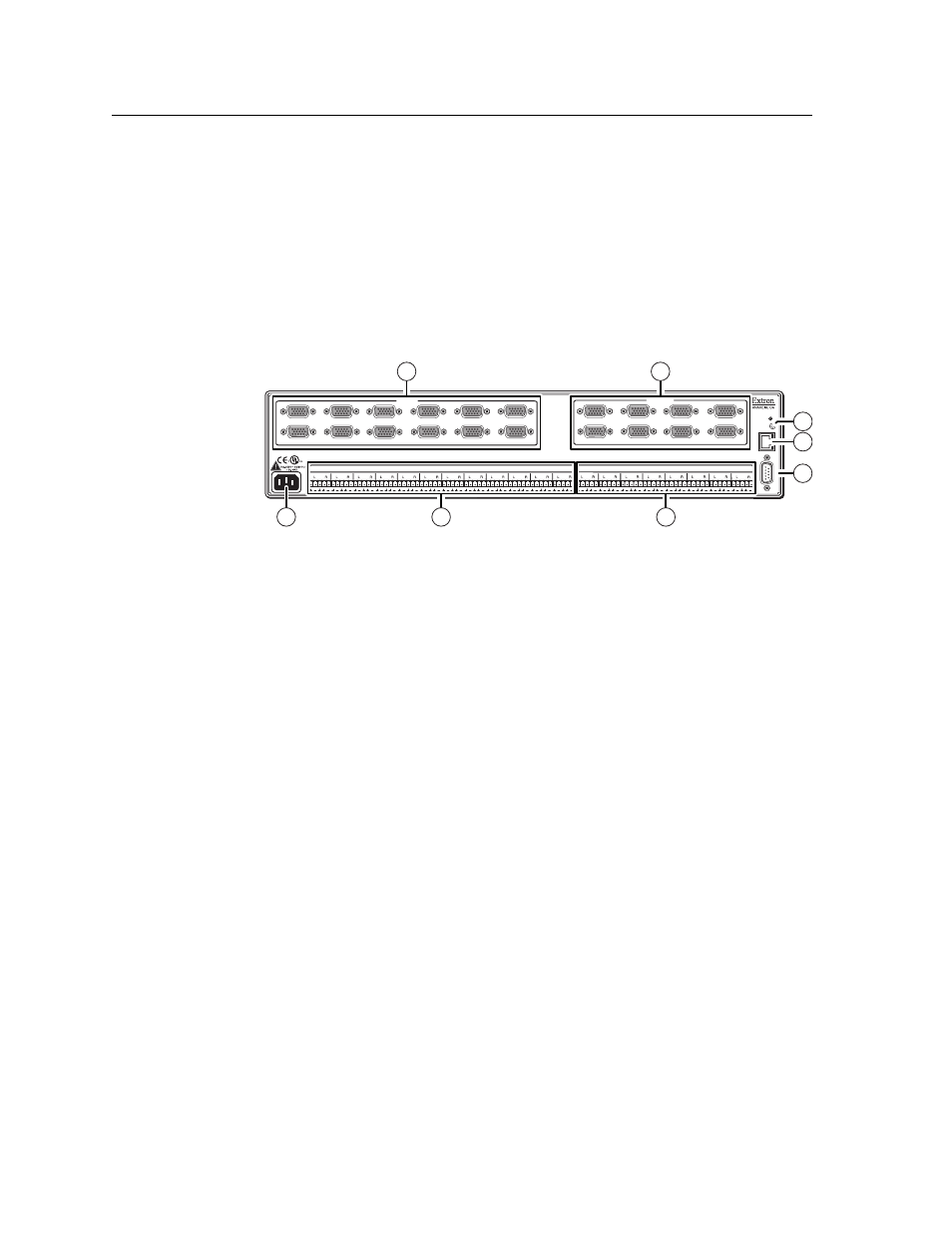
All connectors are on the rear panel. Figure 2-1 shows the MVX Plus 128 A.
INPUTS
OUTPUTS
RESET
RS232/RS422
REMO
TE
LISTED
1T23
I.T.E.
1
2
3
4
5
6
7
8
9
10
11
12
LAN
1
2
3
4
5
6
7
8
1
2
3
4
5
6
7
8
9
10
11
12
1
2
3
4
5
6
7
8
INPUTS
OUTPUTS
8
6
7
5
1
2
4
3
REMO
TE
Figure 2-1 — MVX Plus 128 A video and audio matrix switcher
C
Use Electrostatic discharge precautions (be electrically grounded)
when making connections. Electrostatic discharge (ESD) can damage
equipment, even if you cannot feel, see, or hear it.
C
Remove system power before making all connections.
Video connections
N The switchers do not alter the video signal in any way. The signal output by the
switcher is in the same format as the input.
N The MVX Plus 128 switchers can also switch RGBS, RGsB, RsGsBs,
component video, S-video, or composite video by using the appropriate adapters.
a
RGB video inputs — Connect the analog computer-video sources to these
15-pin HD female connectors.
N Most laptop or notebook computers have an external video port, but they require
special commands to output the video to that connector. Also, a laptop’s screen
shuts off once that port is activated. See the computer’s user’s guide for details,
or contact Extron for a list of common laptop keyboard commands.
b
RGB video outputs — Connect RGBHV video displays to these 15-pin HD
female connectors for each output.