4 installation, 5 id, beeper and led settings – GeoVision GV-R1352 Card Reader (13.56 MHz) User Manual
Page 69
60
⚫
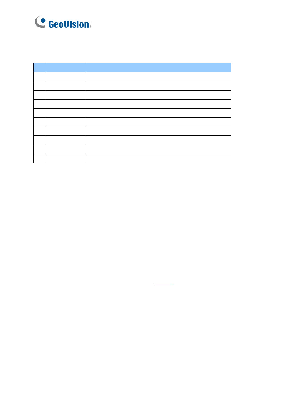
Data Cable:
Connect the reader to GV-AS Controller based on the following pin
definitions:
No
Wire Color
Description
1
Black
DC Power 0 V (GND)
2
Red
DC Power 12V
3
Purple
Beeper Input (Low Sound)
4
Brown
Green LED
5
Yellow
Red LED
6
White
N/A
7
Green
Wiegand Data 0
8
Blue
Wiegand Data 1
9
Gray
RS-485 (A+)
10
Orange
RS-485 (B-)
7.4 Installation
1. Using a self-prepared flat head screwdriver, pry apart the back cover from the
enclosure's edge.
2. Connect the supplied Data Cable to the reader.
3. Secure the reader onto the wall with 2 self-prepared screws.
7.5 ID, Beeper and LED Settings
The
QR1352/ DES1352/R1354
Setup AP
allows you to set the reader
’s ID number, beeper
and LED. The program can be downloaded from o
A single RS-485 interface on the controller can connect up to 8 readers. In order for the
controller to detect multiple connected readers, you must assign each one a unique ID
number.
The reader will beep by default when a card approaches,
whether granted or rejected.
You
can alter how the reader reacts when approached using the Setup AP, from a beep to a
blinking red or green LED.