3 connect the reader to gv-as controller, 1 connect through wiegand interface – GeoVision GV-R1352 Card Reader (13.56 MHz) User Manual
Page 26
GV-RK1352 / R1352 / DFR1352
17
2
2.3 Connect the Reader to GV-AS Controller
You can connect the readers to GV-AS Controllers through Wiegand or RS-485 interface.
Note that the connection between the reader and GV-AS Controller varies among controller
models. For the number of readers supported by a variety of GeoVision controllers, see the
Note:
1.
GV-RK1352 / R1352 / DFR1352 is compatible with GV-AS100 / 1010 / 110 / 120 / 210
/ 2110 / 2120 / 410 / 4110 / 810 / 8110, GV-AS1620, GV-CS1320. However, to enable
the
keypad
function on GV-RK1352, you can only connect GV-RK1352 to the
controllers through the following interfaces.
•
GV-AS100 / 110 / 120: Wiegand
•
GV-AS1010: RS-485
•
GV-AS210 / 2110 / 2120 / 410 / 4110 / 810 / 8110: Wiegand and RS-485
•
GV-AS1620: Wiegand and RS-485
•
GV-CS1320: RS-485
2.
Each GV-RK1352 / R1352 / DFR1352 consumes 60 mA of power. The total power
consumption of the output devices and readers connected to GV-AS Controller must
be under
2.5A
(for GV-CS1320),
3A
(for GV-AS1620, GV-AS210 / 2110 / 2120),
3.5A
(for GV-AS410 / 4110) or
5A
(for GV-AS810 / 8110). Connect an external power
supply if the power supplied from GV-AS Controller is insufficient.
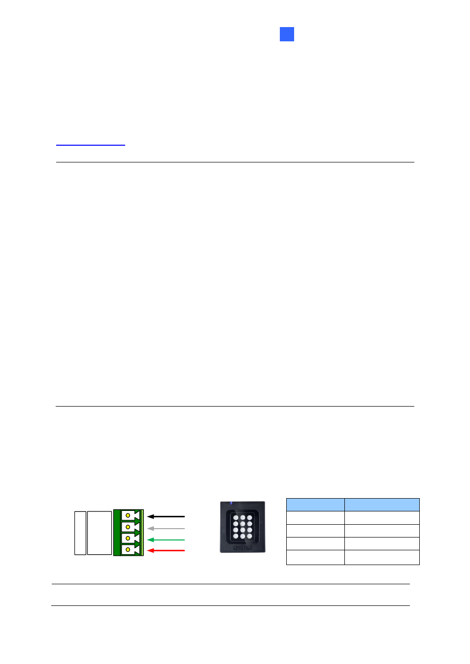
2.3.1 Connect through Wiegand Interface
The following diagrams use
GV-RK1352
and
GV-AS810 Controller
as an example. Up to
eight readers can be connected to GV-AS810 Controller through the controller
’s Wiegand
interface.
(Black)
(Green)
(White)
(Red)
GND
D1
D0
12V
W
ie
g
a
n
d
A
GV-AS810 Controller
GV-RK1352
or GV-R1352
Wire Color
Function
Black
GND
White
Wiegand Data 1
Green
Wiegand Data 0
Red
DC 7.5 ~ 12V
Note:
Connection through
Wiegand interface is not supported for GV-AS1010.