4 installation – GeoVision GV-R1352 Card Reader (13.56 MHz) User Manual
Page 47
38
3.4 Installation
Before the hardware installation, refer to
Physical Descriptions
for the Node ID settings.
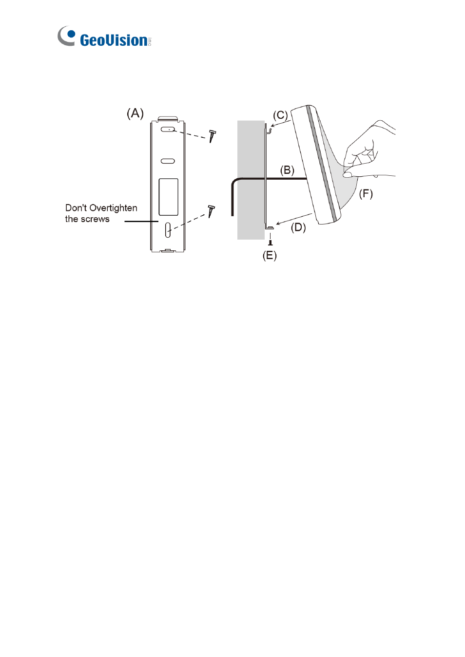
A.
Mount the backplate onto the wall or back box (US standard 120 type). Note DO NOT
overtighten the backplate screws during installation to prevent distortion.
B.
Connect the wires in accordance with the
Wiring Note
below.
C. Make sure the backplate and the upper cover guide of the reader are aligned.
D. Install the upper cover of the reader to the backplate.
E.
Fasten the screw onto the bottom of the reader.
F.
Tear off the protective film.
Wiring Note:
1.
Use minimum 22 AWG double-shielded aluminum mylar foil twisted pair cable for the
connection between the reader and the controller.
2.
In order to reduce long distance noise, the isolated net of transmission cable should
connect to both ends of device ground.
3.
The distance between two readers should be over 30 cm to prevent radio frequency
interference from each other.
4.
Mounting the reader around metal could affect read range. Metal of any type around the
reader should be avoided while mounting.
5.
The distance between the reader and the controller should not exceed 30 meters (98 ft)
(for Wiegand model only).
6.
For optimum read range, use DC Linear power adaptor for the reader's power supply.
7.
In order to ensure the reader's normal operation, input voltage should be 12V±10%.