GeoVision GV-R1352 Card Reader (13.56 MHz) User Manual
Page 12
GV-Reader1251 / 1352 V2 and GV-SR1251
3
1
◼
SW2-SW3 Green/Red LED Control:
The default mode for the Green/Red LED Control
is the internal control. The LED is normally red. When a card is read, the LED flashes
green. When the setting is
“Off”, the Green/Red LED is controlled externally. The
external control lines can then be used to operate the LEDs.
◼
SW4 Master/Slave:
The switch is used to select the Rea
der’s communication interface.
When the setting
is “On”, the Reader is controlled by Wiegand signal. When the setting
is “Off”, the Reader is for RS-485 signal.
◼
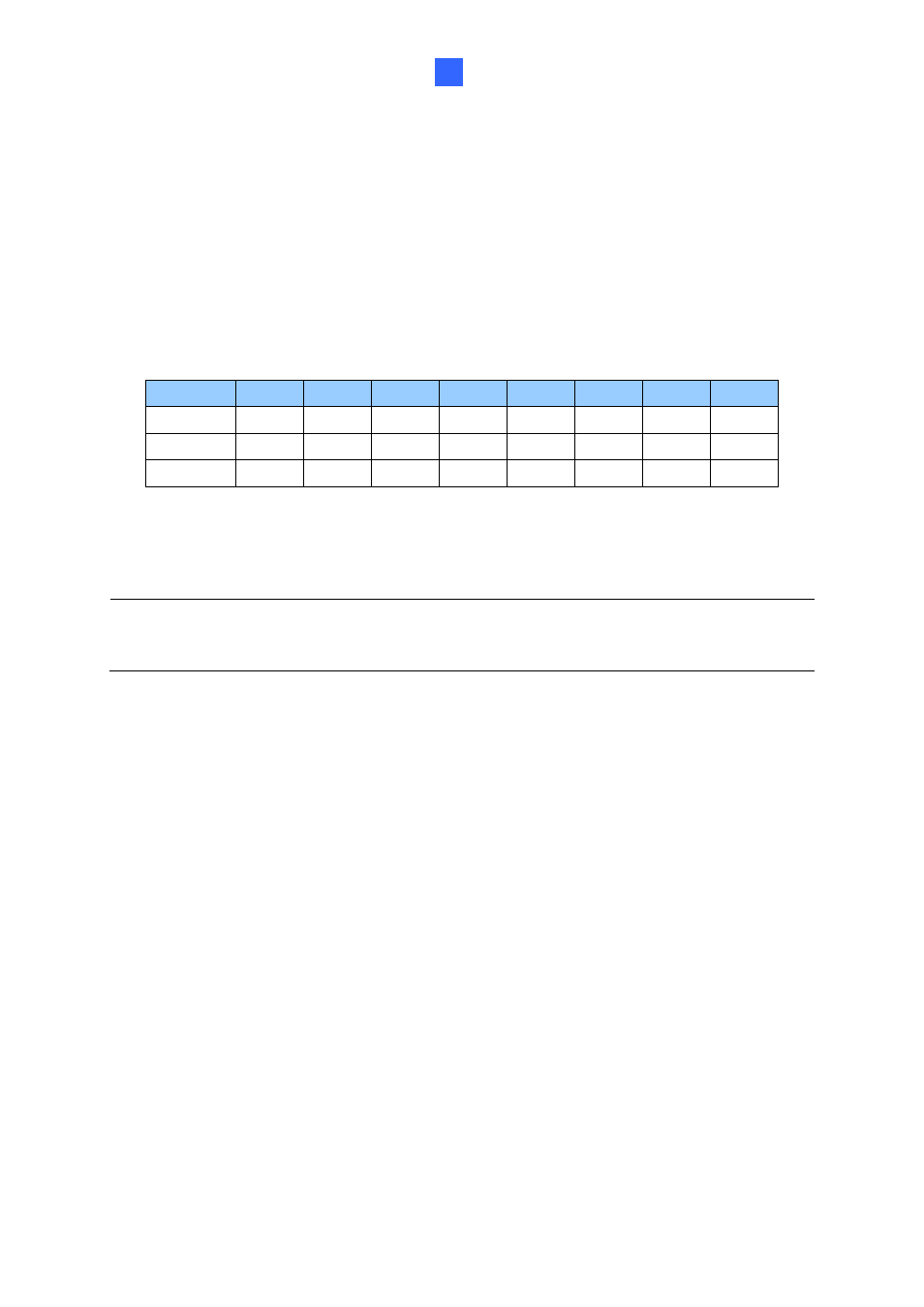
SW5-SW7 ID Setting:
Switch 5 to switch 7 is used to set the R
eader’s ID for wiring in a
daisy chain.
ID
0
1
2
3
4
5
6
7
SW5
OFF
OFF
OFF
OFF
ON
ON
ON
ON
SW6
OFF
OFF
ON
ON
OFF
OFF
ON
ON
SW7
OFF
ON
OFF
ON
OFF
ON
OFF
ON
◼
SW8 RS-485 Terminal Resistor:
When the setting i
s “On,” a 120-ohm resistor is
connected between RS-485+ and RS-485-. This setting is used in the last device when
multiple RS-485 devices are connected together.
Note:
After changing the dip switch settings, the unit must be reset by powering down then
up again before the new switch setting will take effect.