6 control the beeper and led, 1 enable external control on the reader – GeoVision GV-R1352 Card Reader (13.56 MHz) User Manual
Page 35
26
2.6 Control the Beeper and LED
You can configure GV-AS Controller (AS210 / 2110 / 2120 / 410 / 4110 / 810 / 8110) to
control the reader's beeper or LED externally. Through the controller's Web interface, you
can configure the controller to activate the reader's red LED, green LED, or beeper in
response to a specific alert event.
For this function to work, follow the steps in the three sections below:
1. Enable external control of the beeper or LED by using GV-R/RK/DFR Setup AP. See
section 2.6.1.
2. Connect the control wires of the beeper, Red LED or Green LED to the controller. See
section 2.6.2
.
3. Define the beeper or LED for each door through the controller
’s Web interface. See
section 2.6.3
.
Note:
GV-AS1620 can also externally control the reader
’s LED and Beeper for access
granted and denied. For details, see
GV-AS1620 User
’s Manual
.
IMPORTANT:
When GV-RK1352 / R1352 / DFR1352 / SR1251 is connected to a
controller via an RS-485 connection, external control of the LED and beeper is not
supported.
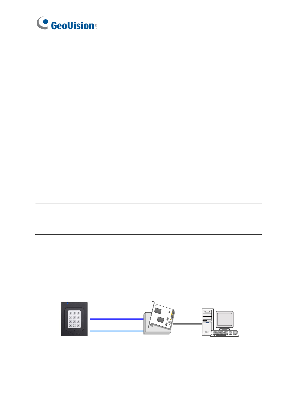
2.6.1 Enable External Control on the Reader
To enable external control of the reader
’s Beeper or LED, first connect the reader to a
computer through a RS-485 / USB converter (e.g. GV-COM, GV-Hub or GV-NET/IO Card
V3.1) as illustrated below.
GV-HUB / GV-COM /
GV-NET/IO Card
PC
(Light Blue) RS-485 -
(Blue) RS-485 +
USB
GV-RK1352