ProSoft Technology MVI56-PDPMV1 User Manual
Page 237
MVI56-PDPMV1 ♦ ControlLogix Platform
Reference
PROFIBUS DPV1 Master
User Manual
ProSoft Technology, Inc.
Page 237 of 255
March 22, 2011
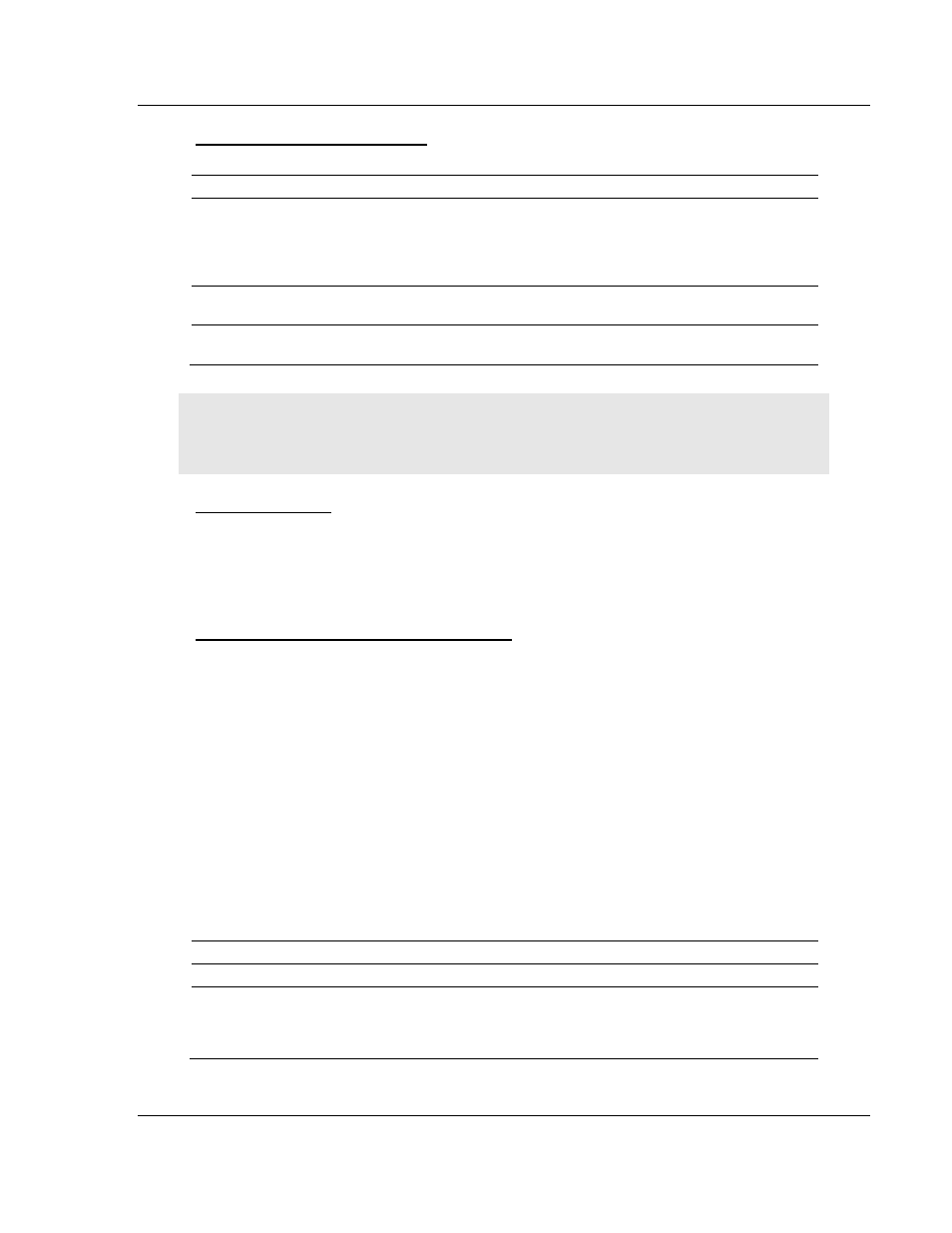
Block ID Numbers for Transfer
Block
Type
Description
0
Input Data
This block is generated only if the module has a single input block
(the configured PROFIBUS input data fits into one input backplane
block). It allows the switching between two blocks with different
block IDs but with same content. So in fact block 0 and block 1 will
transfer the same PROFIBUS input data.
1 to n
Input Data
Input data from PROFIBUS network with each block containing up
to 242 words of data (refer to Input Data Block (page 237))
1 to n
Output Data
Output data for PROFIBUS network with each block containing up
to 243 words of data (refer to Output Data Block (page 242))
Note: The maximum block count n will depend on the configured PROFIBUS I/O size and the
backplane block size for each application. For example, if the PROFIBUS input = 100 and each
backplane block will transfer 20 words of PROFIBUS data, then n=5.
Normal Operation
The MVI56-PDPMV1 module’s application code initiates the data transfers at the
end of every ControlLogix PLC ladder scan. As such, the MVI56-PDPMV1
module is able to actively read and write the PROFIBUS Cyclic Input/Output data
blocks in the appropriate locations.
Input Initialization Block (Block ID = 9990)
Block 9990 is the first block transferred by the module to the processor after one
of the following events:
Module power up
Module configuration through ProSoft Configuration Builder
Module reboot
ControlLogix mode switch from PROG to RUN
It contains general module configuration data, which allows the ladder logic to
correctly handle the handshaking between module and processor for proper
backplane communication.
Input Data Block Format (Input Image) (Local:1:I.Data Controller Tag)
You can find the contents of the Input Data Block (Input Image) in the
Local:1:I.Data user controller tags in RSLogix.
Word Offset
Start
End
Name
Description
0
0
Block Write ID
Block ID of the next write block. It will contain
a value of 9990 because the module expects
the next block from the processor to have the
same block ID.