ProSoft Technology MVI56-PDPMV1 User Manual
Page 229
MVI56-PDPMV1 ♦ ControlLogix Platform
Reference
PROFIBUS DPV1 Master
User Manual
ProSoft Technology, Inc.
Page 229 of 255
March 22, 2011
5.4
Module Functional Overview
The MVI56 module communicates with the processor over the backplane using
only the following two blocks of data:
MVI56 Input Data block
MVI56 Output Data block
This section of the Application Reference Guide describes the data structures
and transfer mechanisms used to transfer data between the MVI56-PDPMV1
module and the ControlLogix processor.
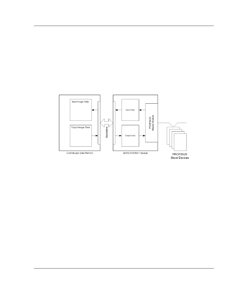
The following illustration shows the Input/Output Data block flow between the
ControlLogix processor and the MVI56-PDPMV1 module.
These two data blocks (Input Data and Output Data) consist of a data structure
that provides for the movement of:
Input Data image from PROFIBUS slave devices
Output Data image for writing to PROFIBUS slave devices
Module configuration and status (from module to processor)
PROFIBUS Messaging Mailbox commands (from processor to module)
PROFIBUS Messaging Mailbox responses (from module to processor)
In LEGACY mode, the module reports this information through regular I/O blocks.
In FLEX mode, this data is exchanged through MSG instructions.
The transfer method depends on the configured mode:
LEGACY (page 230) (firmware version 0.30 or version 1.21 or later and Use
Legacy Mode = Yes)
FLEX (page 236) (firmware version 1.21 or later and Use Legacy Mode = No)