2 programming with external resistance, Programming with external resistance -30, Analog programming of output voltage or – KEPCO KLP Series (older -1200 models) Operator Manual User Manual
Page 70: Current using resistance -30, Ar. 3.7.2, Ar. 3.7.2), 2 for r, D 3.7.2 for
3-30
KLP073008
3.7.2
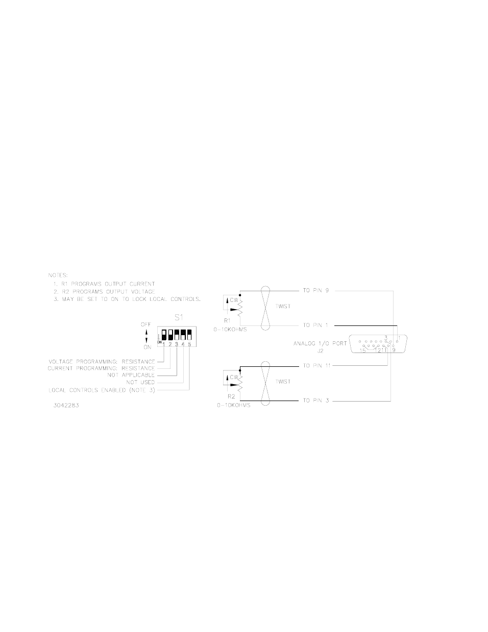
PROGRAMMING WITH EXTERNAL RESISTANCE
Figure 3-6 is a simplified diagrams of the KLP showing the switch configuration and external
connections required for analog programming using an external resistance.
1. Overvoltage and Overcurrent settings must be established via either local programming or
digital remote programming prior to initiating Analog Remote programming. (see PAR.
3.7.4.)
2. Turn off power and configure the Analog I/O DIP switch (Figure 2-2) as follows:
SW1: ON (Program output voltage via resistance)
SW2: ON (Program output current via resistance)
SW3: either OFF or ON (disabled when in remote analog programming mode; see
Table 2-2)
SW4: Not used
SW5: Either OFF (Local controls enabled) or ON (Local controls locked)
3. Configure Analog I/O Port J1 (Figure 2-2) by referring to Table 2-6 and Figure 3-6 (grounding
J1 pin 12 enables analog programming).
FIGURE 3-6. ANALOG PROGRAMMING OF OUTPUT VOLTAGE OR
CURRENT USING RESISTANCE
With the power supply configured as shown in Figure 3-6 and assuming the load causes the
power supply to operate in voltage mode, varying external resistor R2 from 0 to 10K causes the
output voltage of the power supply to vary linearly from 0 to full scale, while R1 can be used to
adjust the current limit. When the power supply operates in current mode, R2 will adjust the volt-
age limit and R1 will adjust output current.
Factory default full scale (F.S.) resistance programming is 10K ohms based on F.S. program-
ming voltage of 10V. To set full scale resistance to a lower value, see PAR. 4.3.3 to change the
F.S. programming voltage to a lower value, then adjust based on 1000 ohms/Volt.