Table 2-5. rear terminal block assignments, Rs232 port connector (j3) pin assignments -4, Rear terminal block assignments -4 – KEPCO KLP Series (older -1200 models) Operator Manual User Manual
Page 30: Analog i/o connector (j2) pin assignments -4
2-4
KLP-HV 073008
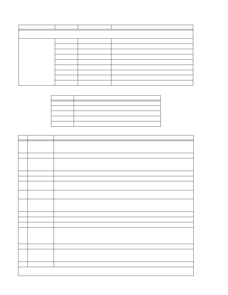
TABLE 2-4. RS232 PORT CONNECTOR (J3) PIN ASSIGNMENTS
CONNECTOR
PIN
SIGNAL NAME
FUNCTION
NOTE: A null modem cable (see Table 1-4) is required for nearly all applications, with the exception of those in which RXD and
TXD line transposition is accomplished via external hardware (e.g. older Apple MAC computers with D-sub serial port).
RS232-C
PORT
1
SGND
Signal Ground
2
RXD
Receive Data
3
TXD
Transmit Data
4
DTR
Data Terminal Ready (protocol not used)
5
SGND
Signal Ground
6
DSR
Data Set Ready (protocol not used)
7
RTS
Request To Send (protocol not used)
8
CTS
Clear To Send (protocol not used)
9
SGND
Signal Ground
TABLE 2-5. REAR TERMINAL BLOCK ASSIGNMENTS
TERMINAL
FUNCTION
M+
Positive output monitor connection (TB5) (see PAR. 2.7.5.1)
S+
Positive sense connection (TB4) (see PAR. 2.7.5.1)
CS
Current Share bus (TB3) (see PAR. 2.7.7.1)
S-
Negative sense connection (TB2) (see PAR. 2.7.5.1)
M-
Negative output monitor connection (TB1) (see PAR. 2.7.5.1)
TABLE 2-6. ANALOG I/O CONNECTOR (J2) PIN ASSIGNMENTS
PIN
SIGNAL NAME
FUNCTION
1
Cref
Analog signal which programs output current from zero to full scale. Voltage or resistance programming
is selected via DIP switch position 2 (See Table 2-2). Refer to PAR. 3.7.3 for voltage programming and
3.7.2 for resistance programming.
2
RELAY_NO
Connected to RELAY_COM (pin 4) for relay energized condition. (1)
3
Vref
Analog signal which programs output voltage from zero to full scale. Voltage or resistance program-
ming is selected via DIP switch position 1 (See Table 2-2). Refer to PAR. 3.7.3 for voltage programming
and 3.7.2 for resistance programming.
4
RELAY_COM
Relay common. (1)
5
Reserved.
6
VOLT_RBACK
Analog signal which represents output voltage from zero to full scale. The full scale programming level
sets the full scale readback level (see PAR. 4.3.3).
7
CURR_RBACK
Analog signal which represents output current from zero to full scale. The full scale programming level
sets the full scale readback level (see PAR. 4.3.3).
8
REM_INH
Allows single signal to control output on/off. See PAR. 3.7.1.
0 = Output is off
1 = Output is on (default, no connection)
9
GND
Ground
10
RELAY_NC
Connected to RELAY_COM (pin 4) for relay not energized condition (1)
11
GND
Ground
12
ANALOG_CTRL
Enables or disables analog programming (see PAR. 3.7).
1 = Analog programming disabled (default, no connection)
0 = Analog programming accepted (use jumper on mating connector to connect to pin 9, 11, 13 or 15
(ground).
13
GND
Ground
14
EXT_TRG
Performs same function as SCPI *TRG command if unit is programmed via digital remote mode. Tran-
sition from 1 (+5V) to 0 (ground) causes values established by VTRIG and CTRIG commands to
become VSET and CSET (see PAR. 3.3.1.3).
15
GND
Ground
(1) Internal relay may be configured to produce Fault signals at the users discretion. Refer to PAR. 3.2.11.3 to configure internal
relay.