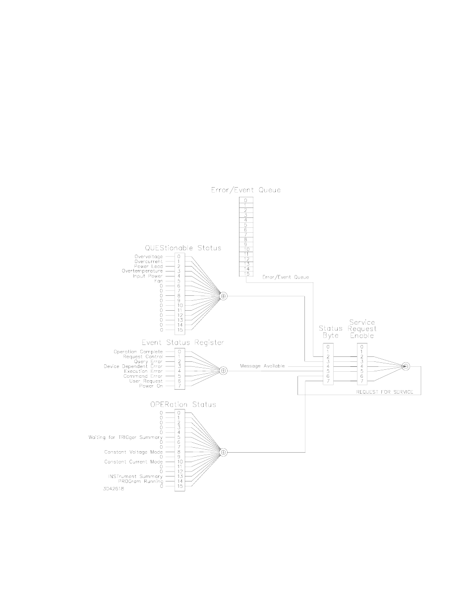
Figure 3-4. status reporting structure, Status reporting structure -27 – KEPCO KLP Series (older -1200 models) Operator Manual User Manual
Page 67
KLP073008
3-27
A zero to one transition of a condition register is added to the event register if the specific bit in
the enable register is also a 1. Reading an event register clears all of the bits found in the event
register. If any bits are set in an event register, the following condition register bit is then set. For
example, if the STAT:QUES:ENB (enable) register has bit 0 set and a voltage error is detected,
the event registers bit 0 is set. The 1 in the event register causes bit 3 of the status byte to be
asserted. The Service Request register is ANDed with its enable register for all bits except bit 6.
The result is placed in bit 6 of the Service Request register. If bit 6 is a 1 (true), it causes the
power supply to assert the SRQ line to the host controller.
Figure 3-4 also shows that if the error/event queue is not empty, bit 3 is set in the Service
Request register and bit 4 indicates that a message is available in the output buffer.
FIGURE 3-4. STATUS REPORTING STRUCTURE