Yaskawa Sigma-5 Large Capacity Users Manual: Design and Maintenance-Rotary Motors-Mechatrolink-III Communication Reference User Manual
Page 56
3 Wiring and Connection
3.1.2 Main Circuit Wire
3-10
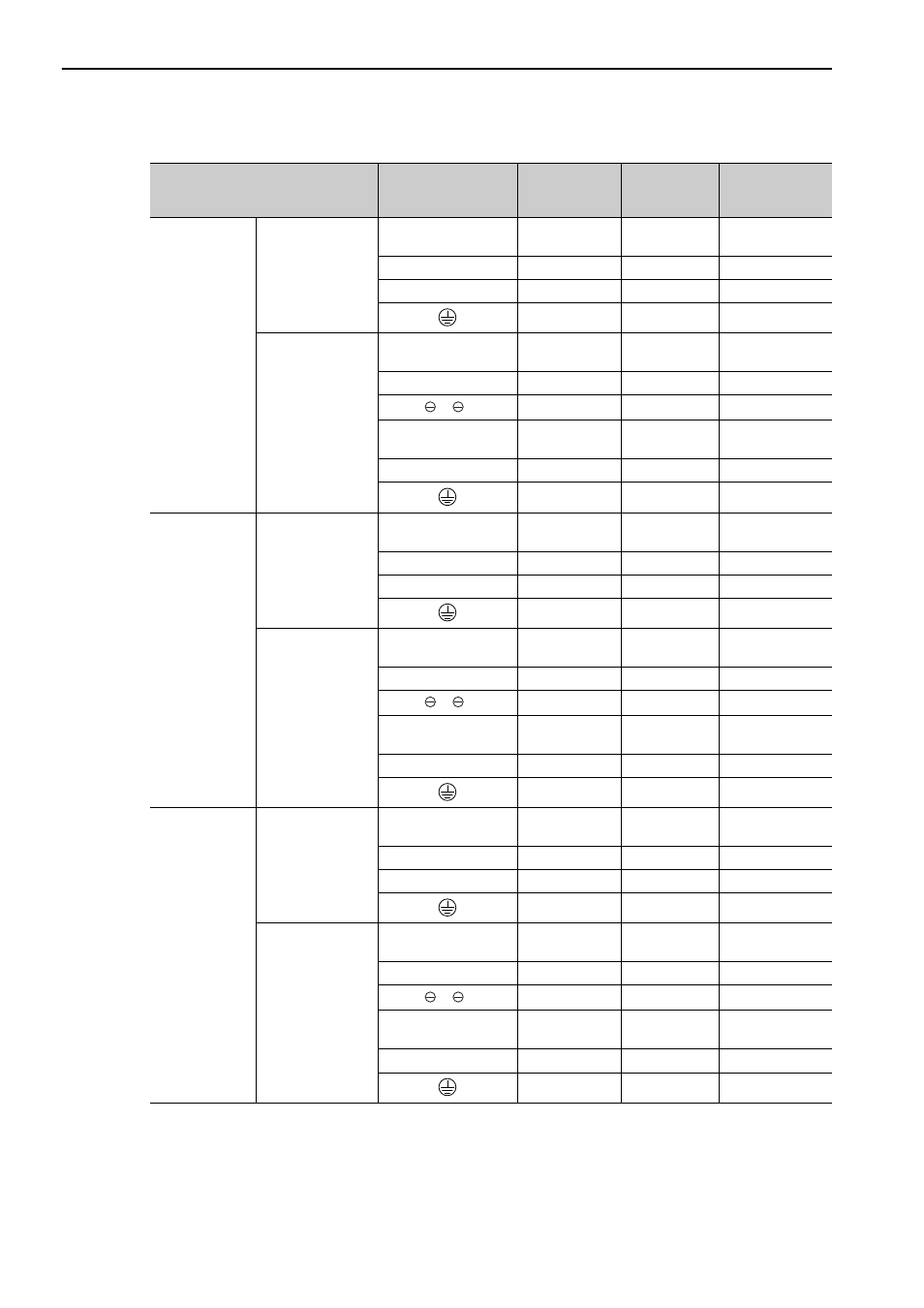
For Three-phase, 400V
∗ Use SERVOPACKs and converters in the specified combinations.
Combination of SERVOPACK and
Converter
*
Terminal Symbols
Screw Size for
Terminals
Tightening
Torque
(N m)
Wire Size AWG
SGDV-750J
SGDV-
COA3ZDA
SERVOPACK
P, N
M8
15.0
Bus bar attached
to the converter
U, V, W
M8
3.0
3
DU, DV, DW
M6
3.0
10
M8
9.0 to 11.0
3
Converter
P, N
M8
3.0
Bus bar attached
to the converter
L1, L2, L3
M8
3.0
3
1, 2
M8
3.0 3
CN101
(24 V, 0 V)
–
(Connector)
–
14
B1, B2
M8
3.0
8
M8
9.0 to 11.0
3
SGDV-101J
SGDV-
COA5EDA
SERVOPACK
P, N
M8
15.0
Bus bar attached
to the converter
U, V, W
M8
3.0
1
DU, DV, DW
M6
3.0
10
M8
9.0 to 11.0
1
Converter
P, N
M10
12 to 20
Bus bar attached
to the converter
L1, L2, L3
M10
12 to 20
2
1, 2
M10
12 to 20
2
CN101
(24 V, 0 V)
–
(Connector)
–
14
B1, B2
M10
12 to 20
8
M8
9.0 to 11.0
2
SGDV-131J
SGDV-
COA5EDA
SERVOPACK
P, N
M10
12 to 20
Bus bar attached
to the converter
U, V, W
M10
30.0
2/0
DU, DV, DW
M6
3.0
10
M8
9.0 to 11.0
2/0
Converter
P, N
M10
12 to 20
Bus bar attached
to the converter
L1, L2, L3
M10
12 to 20
2/0
1, 2
M10
12 to 20
2/0
CN101
(24 V, 0 V)
–
(Connector)
–
14
B1, B2
M10
12 to 20
4
M8
9.0 to 11.0
2/0