Yaskawa Sigma-5 Large Capacity Users Manual: Design and Maintenance-Rotary Motors-Mechatrolink-III Communication Reference User Manual
Page 383
10 Appendix
10.1.2 Parameters
10-34
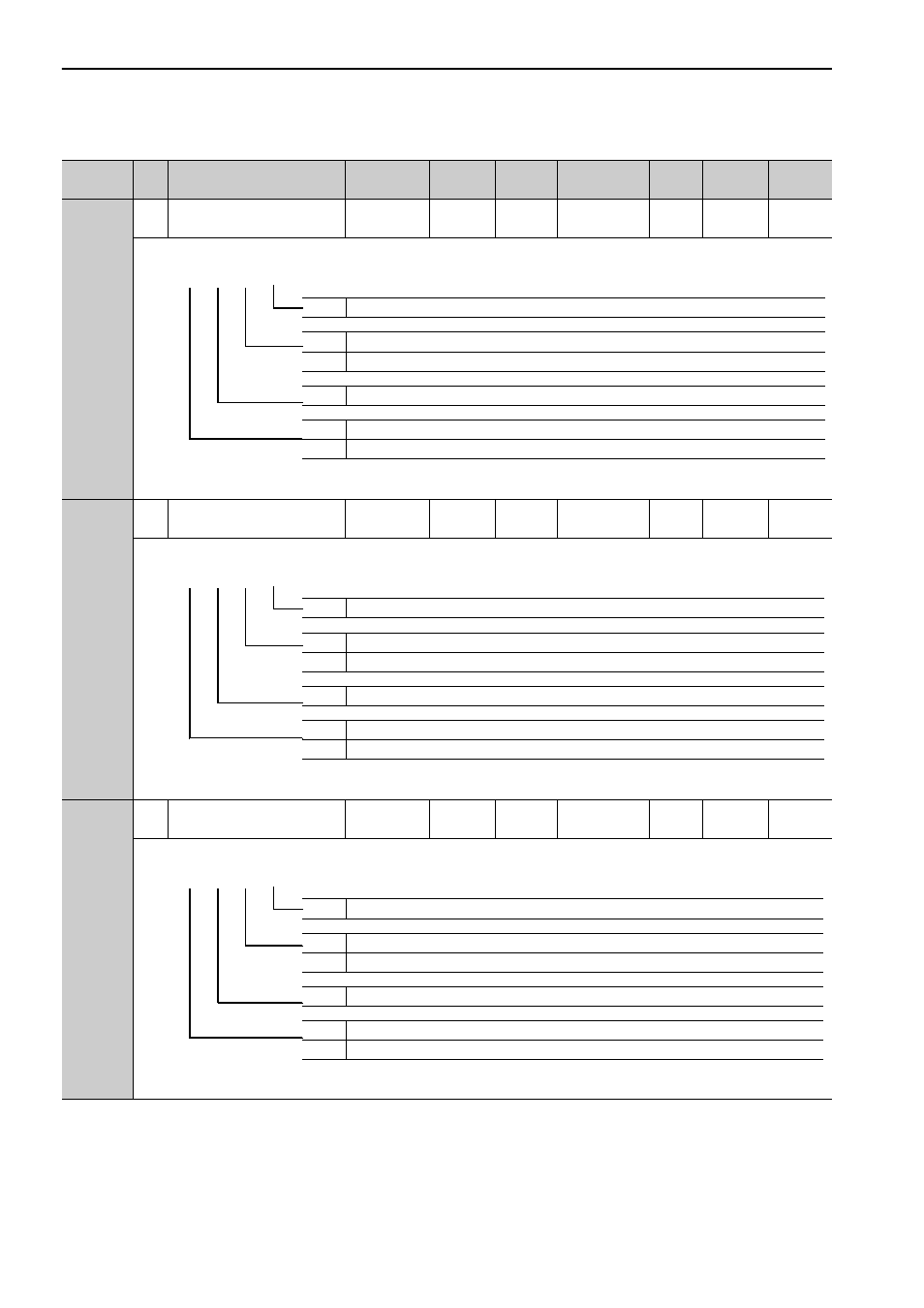
Pn860
2
SVCMD_IO (input signal
monitor) Allocation 1
0000 to 1717
–
0000
Immediately
Setup
M3
*10
–
Pn861
2
SVCMD_IO (input signal
monitor) Allocation 2
0000 to 1717
–
0000
Immediately
Setup
M3
*10
–
Pn862
2
SVCMD_IO (input signal
monitor) Allocation 3
0000 to 1717
–
0000
Immediately
Setup
M3
*10
–
∗10. This parameter is enabled only for MECHATROLINK-III standard servo profile.
(cont’d)
Parameter
No.
Size
Name
Setting
Range
Units
Factory
Setting
When
Enabled
Classi-
fication
Profile
Reference
Section
0 to 7
Bit position of CN1-40 input terminal monitor
0
Disables bit allocation for CN1-40 input terminal monitor.
1
Enables bit allocation for CN1-40 input terminal monitor.
0 to 7
Bit position of CN1-41 input terminal monitor
0
Disables bit allocation for CN1-41 input terminal monitor.
1
Enables bit allocation for CN1-41 input terminal monitor.
4th 3rd 2nd 1st
digit digit digit digit
n.
0 to 7
Bit position of CN1-42 input terminal monitor
0
Disables bit allocation for CN1-42 input terminal monitor.
1
Enables bit allocation for CN1-42 input terminal monitor.
0 to 7
Bit position of CN1-43 input terminal monitor
0
Disables bit allocation for CN1-43 input terminal monitor.
1
Enables bit allocation for CN1-43 input terminal monitor.
4th 3rd 2nd 1st
digit digit digit digit
n.
0 to 7
Bit position of CN1-44 input terminal monitor
0
Disables bit allocation for CN1-44 input terminal monitor.
1
Enables bit allocation for CN1-44 input terminal monitor.
0 to 7
Bit position of CN1-45 input terminal monitor
0
Disables bit allocation for CN1-45 input terminal monitor.
1
Enables bit allocation for CN1-45 input terminal monitor.
4th 3rd 2nd 1st
digit digit digit digit
n.