5 servopack and converter internal block diagrams, 1 three-phase 200 v, M-iii – Yaskawa Sigma-5 Large Capacity Users Manual: Design and Maintenance-Rotary Motors-Mechatrolink-III Communication Reference User Manual
Page 32
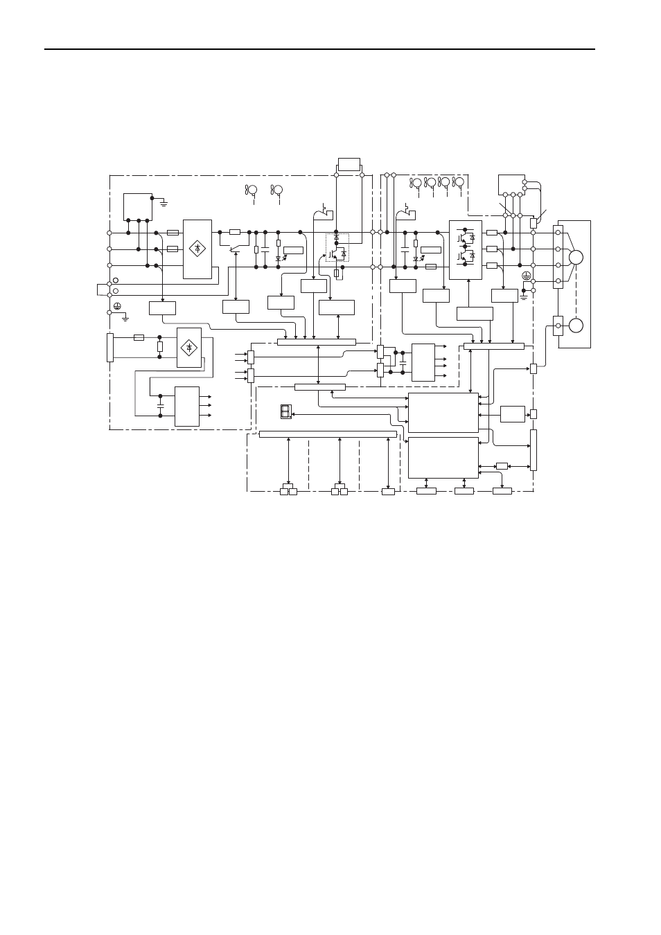
1 Outline
1.5.1 Three-phase 200 V
1-10
1.5 SERVOPACK and Converter Internal Block Diagrams
1.5.1 Three-phase 200 V
L1
+
B2
L2
U
V
W
- 1
L3
drive
MC
- 2
CHARGE
P24 V
SPD
P
N
+24 V
24C
+24 V
24C
CN103
CN104
CN901
P
N
CHARGE
ENC
M
㧗
㧙
CN103
CN104
P24 V
0 V
CN901
+24 V
6
24 V
+5 V
15 V
CN2
CN6A
CN6B
CN21
CN22
CN31
P24 V P24 V P24 V
-
B1
㧗
㧙
DU
DV
DW
CN115
CN5
CN3
CN7
CN8
CN1
I/O
Varistor
L1C
L2C
㧗
㧙
+5 V
+15 V
+24 V
2
㧗
㧙
㧗
㧙
24 V
24 V
Fan 1
Fan 2
Voltage
sensor
Control power supply
Main circuit
power supply
Voltage
sensor
Converter I/O
SERVOPACK
control power supply
Panel display
Feedback option
Safety option
MECHATROLINK
communications
(M-
III
)
Voltage sensor
gate drive
Temperature
sensor
Voltage
sensor
Temperature
sensor
Fan
2
Fan
1
Fan
4
Fan 3
(for 55-kW
models only)
Control
power
supply
ASIC
(PWM control, etc.)
CPU
(Position and speed
calculation, etc.)
PC
Digital
operator
Safety function
signals
Gate drive
Current
sensor
Dynamic
brake
unit
Analog
voltage
converter
Servomotor
I/O signals
Analog monitor output
Encoder pulse output
Regenerative
resistor unit
Control
power
supply
M-III