11 wiring checklist – Yaskawa R1000 Series Power Regenerative Unit User Manual
Page 66
66
YASKAWA ELECTRIC TOEP C710656 08B YASKAWA Power Regenerative Unit - R1000 Instruction Manual
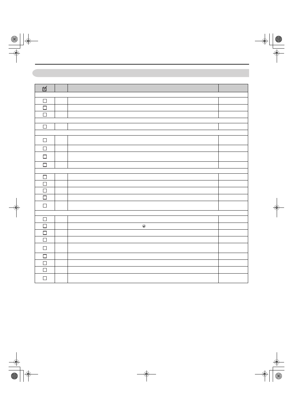
3.11 Wiring Checklist
3.11 Wiring Checklist
No.
Item
Page
Regenerative Unit, Peripherals, Option Cards
1
Check regenerative unit model number to ensure receipt of correct model.
2
Make sure you have the correct peripheral devices.
–
3
Check the option card model number.
–
Installation Area and Physical Setup
4
Ensure that the area surrounding the regenerative unit complies with specifications.
Power Supply Voltage, Output Voltage
5
The voltage from the power supply should be within the input voltage specification range of the
regenerative unit.
–
6
The total load must be within the output specifications of the regenerative unit.
7
A power supply with a capacity (kVA) that is larger than the rated input capacity of the regenerative
unit must be used.
–
8
The ratings must be correct.
Main Circuit Wiring
9
Confirm proper branch circuit protection as specified by national and local codes.
–
10
Properly wire the regenerative unit.
11
Suitable wires must be used to wire the power supply and regenerative unit.
12
Properly ground the regenerative unit. Review page
13
Tighten control circuit and grounding terminal screws.
Refer to
Wire Gauges and Tightening Torque on page 50
Control Circuit Wiring
14
Use twisted-pair line for all regenerative unit control circuit wiring.
15
Ground the shields of shielded wiring to the GND terminal.
16
Properly wire any option cards.
–
17
Check for any other wiring mistakes. Only use a multimeter to check wiring.
–
18
Properly fasten regenerative unit control circuit terminal screws. Refer to
.
19
Pick up all wire clippings.
–
20
Ensure that no frayed wires on the terminal block are touching other terminals or connections.
–
21
Properly separate control circuit wiring and main circuit wiring.
–
22
The line between the input-side AC reactor and regenerative unit must be 10 m or shorter and the DC
bus line between the regenerative unit and drive must be 5 m or shorter.
–
TOEP_C710656_08B_1_0.book 66 ページ 2015年2月5日 木曜日 午前10時7分