3 main circuit connection diagram, 2a03p5 to 2a0053, and 4a03p5 to 4a0073, 2a0073 to 2a0105, and 4a0105 to 4a0300 – Yaskawa R1000 Series Power Regenerative Unit User Manual
Page 40: Main circuit connection diagram
40
YASKAWA ELECTRIC TOEP C710656 08B YASKAWA Power Regenerative Unit - R1000 Instruction Manual
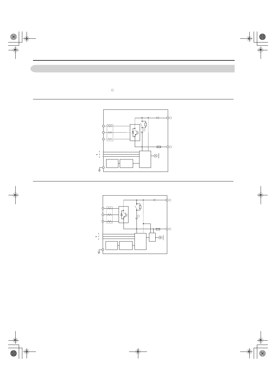
3.3 Main Circuit Connection Diagram
3.3 Main Circuit Connection Diagram
Refer to diagrams in this section when wiring the main circuit of the regenerative unit. Connections may vary based on
regenerative unit capacity. The DC power supply for the main circuit also provides power to the control circuit.
NOTICE: Do not use the negative DC bus terminal “ ” as a ground terminal. This terminal is at high DC voltage potential. Improper
wiring connections could damage the regenerative unit.
◆ 2A03P5 to 2A0053, and 4A03P5 to 4A0073
Figure 3.2
Figure 3.2 Connecting Main Circuit Terminals
◆ 2A0073 to 2A0105, and 4A0105 to 4A0300
Figure 3.3
Figure 3.3 Connecting Main Circuit Terminals
–
–
Relay
DC
Fuse
Gate
board
Control
board
Operator
+
+
Current
sensor
R/L1
S/L2
T/L3
r1/ 11
1/ 21
t1/ 31
YAI
+
R/L1
S/L2
T/L3
+
Current
sensor
Relay
–
DC
Fuse
24 V
Power
Supply
Gate
board
Control
board
Operator
r1/ 11
1/ 21
t1/ 31
YAI
TOEP_C710656_08B_1_0.book 40 ページ 2015年2月5日 木曜日 午前10時7分