Installing standard configuration devises – Yaskawa R1000 Series Power Regenerative Unit User Manual
Page 217
D.3 UL Standards
YASKAWA ELECTRIC TOEP C710656 08B YASKAWA Power Regenerative Unit - R1000 Instruction Manual
217
St
and
ar
ds Co
mpl
ia
nce
D
◆ Power Coordinating Reactor/Current Suppression Reactor
To conform to UL508C, connect the power coordinating reactor to the input side of the drive, input fuses, and the current
suppression reactor to the input side of the regenerative unit. Refer to
Standard Configuration Devices on page 204
for
details.
◆ Installing Standard Configuration Devises
NOTICE: If a fuse is open or a Ground Fault Circuit Interrupter (GFCI) is tripped, check the wiring and the selection of the peripheral
devices. Check the wiring and the selection of peripheral devices to identify the cause. Contact Yaskawa before restarting the
regenerative unit or the peripheral devices if the cause cannot be identified.
■
Recommended Standard Configuration Devises
Yaskawa recommends installing standard configuration devises to maintain compliance with UL508C.
Refer to
Standard Configuration Devices on page 204
for details.
■
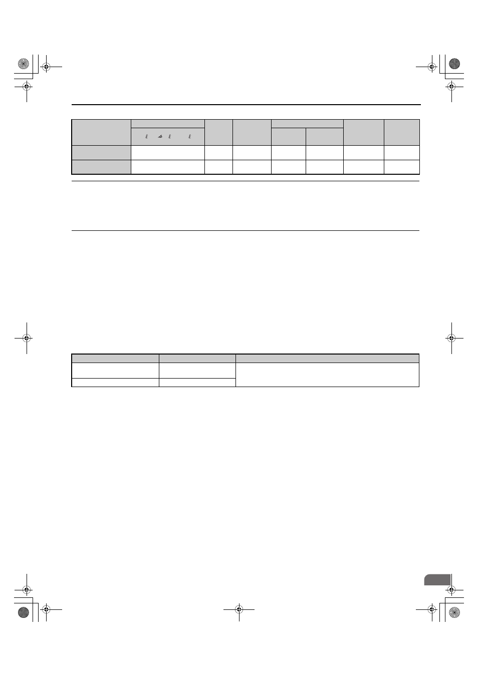
Low Voltage Wiring for Control Circuit Terminals
Wire low voltage wires with NEC Class 1 circuit conductors. Refer to national state or local codes for wiring. The
external power supply shall be a CSA certified or cUL Listed Class 2 power source only or equivalent.
Table D.5 Control Circuit Terminal Power Supply
■
Regenerative Unit Short-Circuit Rating
This regenerative unit is suitable for use on a circuit capable of delivering not more than 100,000 RMS symmetrical
amperes, 240 Vac for 200 V class regenerative units and 480 Vac for 400 V class regenerative units, when protected by
fuses as specified on the
.
Connect the regenerative unit to an AC drive which has built-in semiconductor short-circuit protection and conforms to
UL short-circuit test.
Model
Wire Gauge (AWG, kcmil)
Screw
Size
Crimp
Terminal
Model
Number
Tool
Insulation
Cap
Model No.
Code
r1/ 11, 1/ 21,
t1/ 31
Machine
No.
Die Jaw
2A03P5 to 2A0028,
4A03P5 to 4A0028
14
M3.5
R2-3.5
YA-4
AD-900
TP-003
100-106-516
2A0035 to 2A0105,
4A0035 to 4A0300
14
M4
R2-4
YA-4
AD-900
TP-003
100-106-517
Input / Output
Terminal Signal
Power Supply Specifications
Multi-function digital inputs
S1, S2, S3, S4, S5, S6, S7, S8,
SC
Use the internal LVLC power supply of the regenerative unit. Use class 2 for
external power supply.
Multi function analog inputs
+V, -V, A1, A2, A3, AC
TOEP_C710656_08B_1_0.book 217 ページ 2015年2月5日 木曜日 午前10時7分