Figure 3.25, Figure 3.27 – Yaskawa R1000 Series Power Regenerative Unit User Manual
Page 62
3.9 Control Circuit Wiring
62
YASKAWA ELECTRIC TOEP C710656 08B YASKAWA Power Regenerative Unit - R1000 Instruction Manual
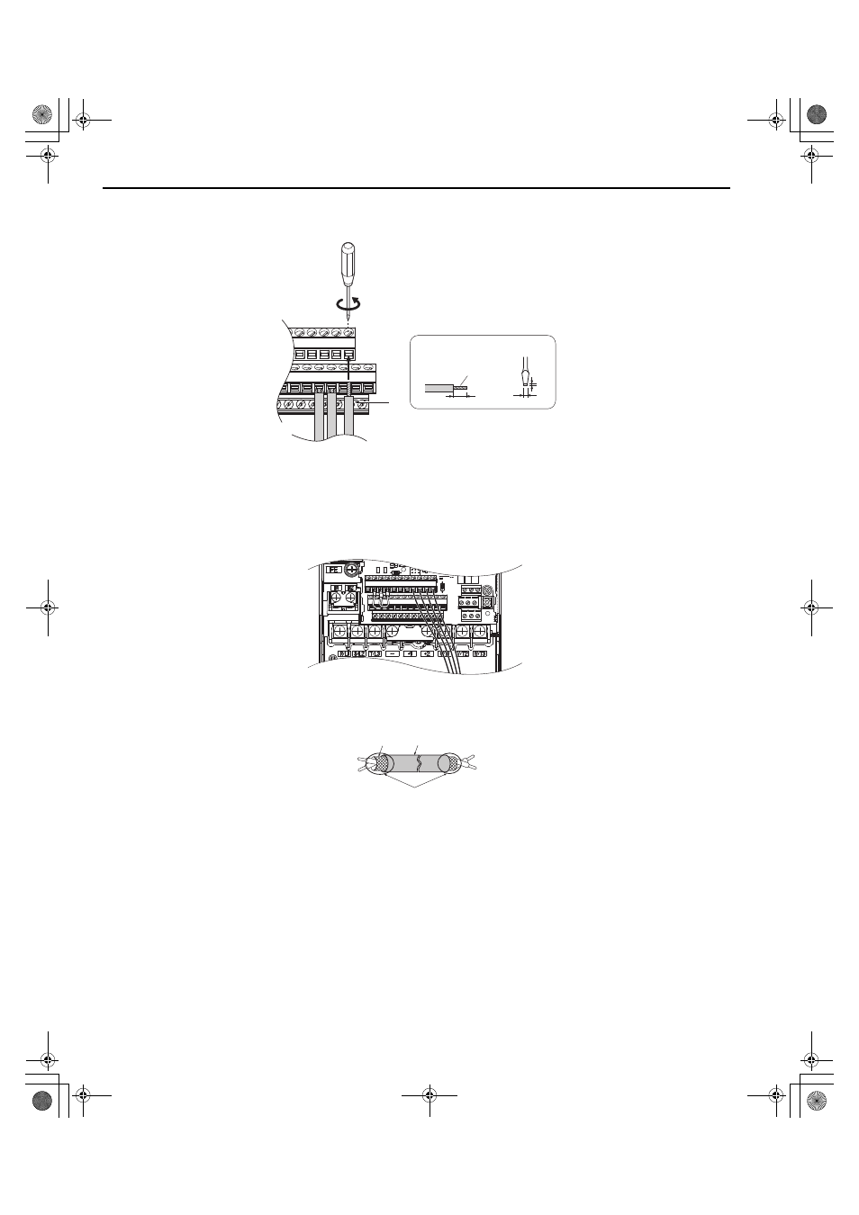
Connect control wires as shown in
Figure 3.22
Figure 3.25 Terminal Board Wiring Guide
Figure 3.23
Figure 3.26 Terminal Board Location Inside the Regenerative Unit
For the control circuit wires, use shielded twisted-pair wires that have been prepared as shown in
.
Figure 3.24
Figure 3.27 Preparing the Ends of Shielded Cables
NOTICE: The analog signal wiring between the regenerative unit and the operator station or peripheral equipment should not exceed
50 meters when using an analog signal from a remote source. Failure to comply could result in poor system performance.
A – Loosen screw to insert wire.
C – Avoid fraying wire strands when
stripping insulation from wire.
Strip length 5.5 mm.
B – Single wire or stranded wire
D – Blade depth of 0.4 mm or less
E – Blade width of 2.5 mm or less
A – Regenerative unit side
D – Shield sheath (insulate with tape)
B – Insulation
E – Shield
C – Control device side
A
B
C
D
Preparing wire
terminal ends
YAI
YAI
A
E
B
C
D
TOEP_C710656_08B_1_0.book 62 ページ 2015年2月5日 木曜日 午前10時7分