Yaskawa R1000 Series Power Regenerative Unit User Manual
Page 163
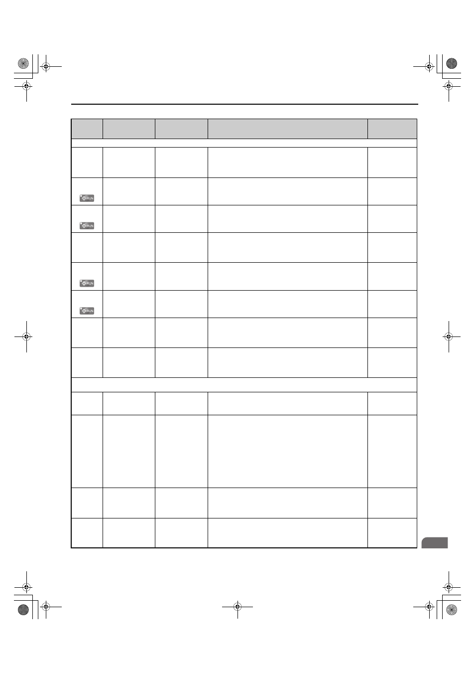
B.2 Parameter Tables
YASKAWA ELECTRIC TOEP C710656 08B YASKAWA Power Regenerative Unit - R1000 Instruction Manual
163
B
No.
(Address
Hex)
Name
LCD Display
Description
Values
H4: Analog Outputs
H4-01
(41DH)
Terminal FM
Monitor Selection
Term FM FuncSel
Selects the data to be output through terminal FM.
Set the desired monitor parameter to the digits available in
U-.
For example, enter “154” for U1-54.
Default: 157
Min.: 000
Max.: 408
H4-02
(41EH)
Terminal FM
Monitor Gain
Terminal FM Gain
Sets the signal level at terminal FM that is equal to 100% of the
selected monitor value.
Default: 100.0%
Min.: -999.9%
Max.: 999.9%
H4-03
(41FH)
Terminal FM
Monitor Bias
Terminal FM Bias
Sets the signal level at terminal FM that is equal to 0% of the
selected monitor value.
Default: 0.0%
Min.: -999.9%
Max.: 999.9%
H4-04
(420H)
Terminal AM
Monitor Selection
Terminal AM Sel
Selects the data to be output through terminal AM.
Set the desired monitor parameter to the digits available in
U-.
For example, enter “154” for U1-54.
Default: 155
Min.: 000
Max.: 408
H4-05
(421H)
Terminal AM
Monitor Gain
Terminal AM Gain
Sets the signal level at terminal AM that is equal to 100% of the
selected monitor value.
Default: 50.0%
Min.: -999.9%
Max.: 999.9%
H4-06
(422H)
Terminal AM
Monitor Bias
Terminal AM Bias
Sets the signal level at terminal AM that is equal to 0% of the
selected monitor value.
Default: 0.0%
Min.: -999.9%
Max.: 999.9%
H4-07
(423H)
Terminal FM Signal
Level Selection
Level Select1
0: 0-10 VDC
1: -10 +10 VDC
2: 4-20 mA
Sets the signal level at terminal FM.
0: 0 to 10 V
1: -10 to 10 V
2: 4 to 20 mA
Default: 0
Min.: 0
Max.: 1
H4-08
(424H)
Terminal AM Signal
Level Selection
AO Level Select2
0: 0-10 VDC
1: -10 +10 VDC
2: 4-20 mA
Sets the signal level at terminal AM.
0: 0 to 10 V
1: -10 to 10 V
2: 4 to 20 mA
Default: 0
Min.: 0
Max.: 1
H5: MEMOBUS/Modbus Serial Communication
Note: Restart the drive to enable MEMOBUS/Modbus communication settings.
H5-01
(0425)
Drive Slave Address Serial Comm Adr
Selects drive station node number (address) for MEMOBUS/
Modbus terminals R+, R-, S+, S-. Cycle power for the setting
to take effect.
Default: 1F (Hex)
Min.: 0
Max.: FF
H5-02
(0426)
Communication
Speed Selection
Serial Baud Rate
0: 1200 bps
1: 2400 bps
2: 4800 bps
3: 9600 bps
4: 19.2 kbps
5: 38.4 kbps
6: 57.6 kbps
7: 76.8 kbps
8: 115.2 kbps
0: 1200 bps
1: 2400 bps
2: 4800 bps
3: 9600 bps
4: 19200 bps
5: 38400 bps
6: 57600 bps
7: 76800 bps
8: 115200 bps
Cycle power for the setting to take effect.
Default: 3
Range: 0 to 8
H5-03
(0427)
Communication
Parity Selection
Serial Com Sel
0: No Parity
1: Even Parity
2: Odd Parity
0: No parity
1: Even parity
2: Odd parity
Cycle power for the setting to take effect.
Default: 0
Range: 0 to 2
H5-04
(0428)
Stopping Method
after
Communication
Error
Serial Fault Sel
0: Ramp to Stop
1: Coast to Stop
3: Alarm Only
0: Ramp to stop
1: Coast to stop
3: Alarm only
Default: 3
Range: 1, 3
TOEP_C710656_08B_1_0.book 163 ページ 2015年2月5日 木曜日 午前10時7分