B: application – Yaskawa R1000 Series Power Regenerative Unit User Manual
Page 156
B.2 Parameter Tables
156
YASKAWA ELECTRIC TOEP C710656 08B YASKAWA Power Regenerative Unit - R1000 Instruction Manual
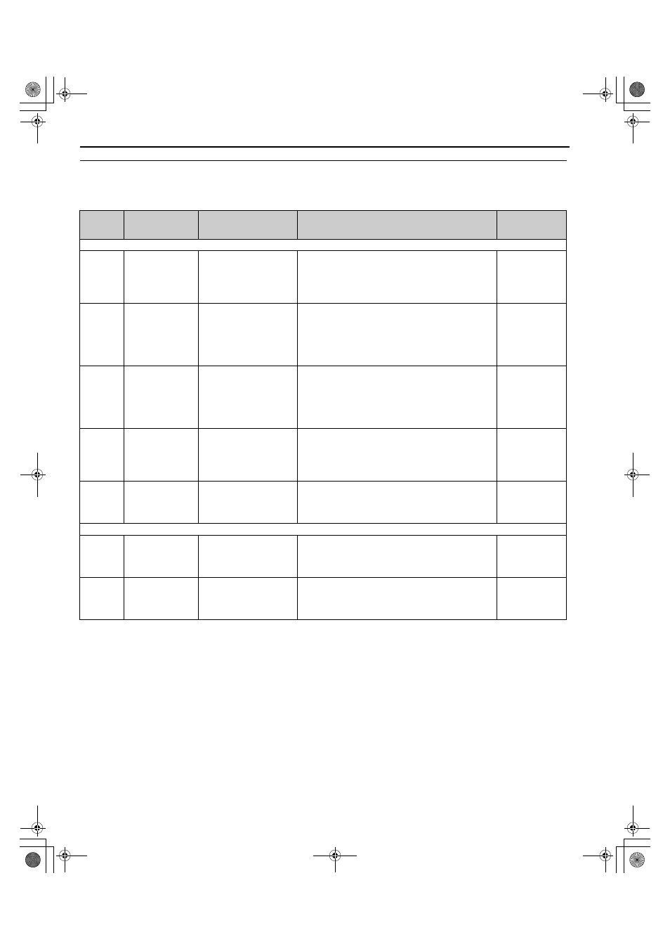
◆ b: Application
Application parameters configure the source of the operation mode selection.
No.
(Address
Hex)
Name
LCD Display
Description
Values
b1: Operation Mode Selection
b1-02
(181H)
Run Command
Selection 1
Run Source 1
0: Digital operator
1: Digital Inputs
2: Communication
3: Option PCB
0: Digital operator
1: Digital input terminals
2: MEMOBUS/Modbus communications
3: Option PCB
Default: 1
Range: 0 to 3
b1-06
(185H)
Digital Input
Reading
Cntl Input Scans
1: Scan
2: Scans
Defines how the digital inputs are read. The inputs are
acted upon every 1 ms or 2 ms depending upon the setting.
0: Input status is read once and processed immediately (for
quicker response)
1: Input is read twice and processed only if the status is the
same in both readings (robust against noisy signals)
Default: 1
Range: 0, 1
b1-08
(187H)
Run Command
Selection in
Programming Mode
RUN dur PRG Mode
0: Run
Disabled@PRG
1: ModeRun
Enabled@PRG
2: Prg only @ Stop
Allow the regenerative unit to run while in Programming
Mode.
0: Run command is not accepted while in Programming
Mode.
1: Run command is accepted while in Programming Mode.
2: Prohibit entering Programming Mode during run.
Default: 0
Range: 0 to 2
b1-17
(1C6H)
Run Command at
Power Up
Run Cmd @ Pwr On
0: Cycle Ext Run
1: Accept Ext Run
Determines whether an external Run command that is
active during power up will start the regenerative unit.
0: Disregarded. A new Run Command must be issued.
1: Allowed. Regenerative unit will start immediately if
Run Command is present at power up.
Default: 0
Range: 0, 1
b1-21
(766H)
Operator Operation
Mode
Run Mode Sel
0: Manual Run
1: Auto run
Sets the operation mode when b1-02 (Run Command
Selection) is set to 0 (LED operator or LCD operator).
0: Forced operation
1: Automatic operation
Default: 1
Range: 0, 1
b4: Timer Function
b4-01
(1A3H)
Timer Function
On-Delay Time
Delay-ON Timer
Sets the on-delay times for a digital timer output
(H2-=12).
The output is triggered by a digital input programmed to
H1-=18.
Default: 0.0 s
Min.: 0.0 s
Max.: 3000.0 s
b4-02
(1A4H)
Timer Function
Off-Delay Time
Delay-OFF Timer
Sets the off-delay times for a digital timer output
(H2-=12).
The output is triggered by a digital input programmed to
H1-=18.
Default: 0.0 s
Min.: 0.0 s
Max.: 3000.0 s
TOEP_C710656_08B_1_0.book 156 ページ 2015年2月5日 木曜日 午前10時7分