Yaskawa R1000 Series Power Regenerative Unit User Manual
Page 107
5.4 Alarm Detection
YASKAWA ELECTRIC TOEP C710656 08B YASKAWA Power Regenerative Unit - R1000 Instruction Manual
107
Tr
ou
blesh
oot
ing
5
Digital Operator
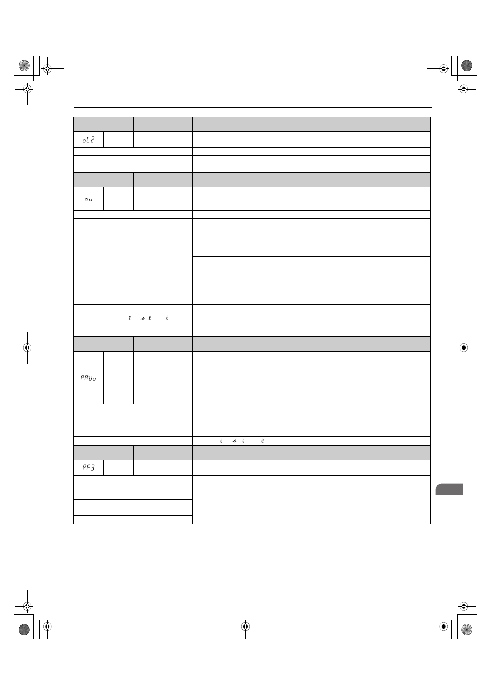
Display
Minor Fault Name
Detail
Alarm Output
(H2- = 10)
oL2
Overload
The thermal sensor of the regenerative unit triggered the unit overload
protection.
YES
Cause
Possible Solutions
Load is too heavy.
Reduce the load.
The regenerative unit does not operate.
Start regenerative unit operation first, and then start regenerative unit operation.
Digital Operator
Display
Minor Fault Name
Detail
Alarm Output
(H2- = 10)
ov
DC Bus Overvoltage
The DC bus voltage exceeded the trip point.
• 200 V Class: Approximately 410 V
• 400 V Class: Approximately 820 V
YES
Cause
Possible Solutions
Electrical noise interference causes the
regenerative unit to operate incorrectly.
• Review possible solutions for handling noise interference.
• Review section on handling noise interference and check control circuit lines, main circuit lines
and ground wiring.
• If the magnetic contactor is identified as a source of noise, install a surge protector to the MC
coil.
Set number of fault restarts (L5-01) to a value other than 0.
There was a regenerative load while the
regenerative unit is stopped.
Operate the regenerative unit.
The power supply voltage is too high.
Lower the voltage so that it is within the power supply specifications of the regenerative unit.
There is a regenerative load while the
regenerative unit is stopped.
Operate the regenerative unit.
The wiring of the power supply voltage
detection circuits (
) and
the wiring of the main circuit terminals (R/L1,
S/L2, and T/L3) is not correct.
Check the wiring.
Correct the wiring.
Digital Operator
Display
Minor Fault Name
Detail
Alarm Output
(H2- = 10)
PAUv
Power Supply
Undervoltage
Pre-Alarm
The input power supply voltage became equal to or lower than the Input Power
Supply Undervoltage Detection Level.
200 V Class: Approximately 150 Vac
400 V Class: Approximately 300 Vac
The regenerative unit enters the baseblock state during pre-alarm. When the
input supply voltage is restored during the pre-alarm, the regenerative unit will
release the base block and continue to operate.
YES
Cause
Possible Solutions
The power supply voltage is low.
Increase the power supply voltage.
A phase loss occurred in the input power
supply.
Check the input power supply for phase loss or an imbalance in the interphase voltages.
Investigate and correct the cause and reset the fault.
Voltage detection failed.
Check r1/ 11, 1/ 21, t1/ 31 to see if they are wired correctly.
Digital Operator
Display
Minor Fault Name
Detail
Alarm Output
(H2- = 10)
PF3
Input Phase Loss
Detection
Abnormal oscillation continued in the input power supply voltage. (Detected
when L8-69 = 1.)
YES
Cause
Possible Solutions
The fluctuation in the voltage of the input
power supply is too large.
Investigate the cause and implement countermeasures.
Refer to
Diagnosing and Resetting Faults on page 112
for details.
A phase loss occurred in the input power
supply.
The interphase voltage balance is bad.
r1/ 11, 1/ 21, t1/ 31
TOEP_C710656_08B_1_0.book 107 ページ 2015年2月5日 木曜日 午前10時7分