Ground wiring – Yaskawa R1000 Series Power Regenerative Unit User Manual
Page 55
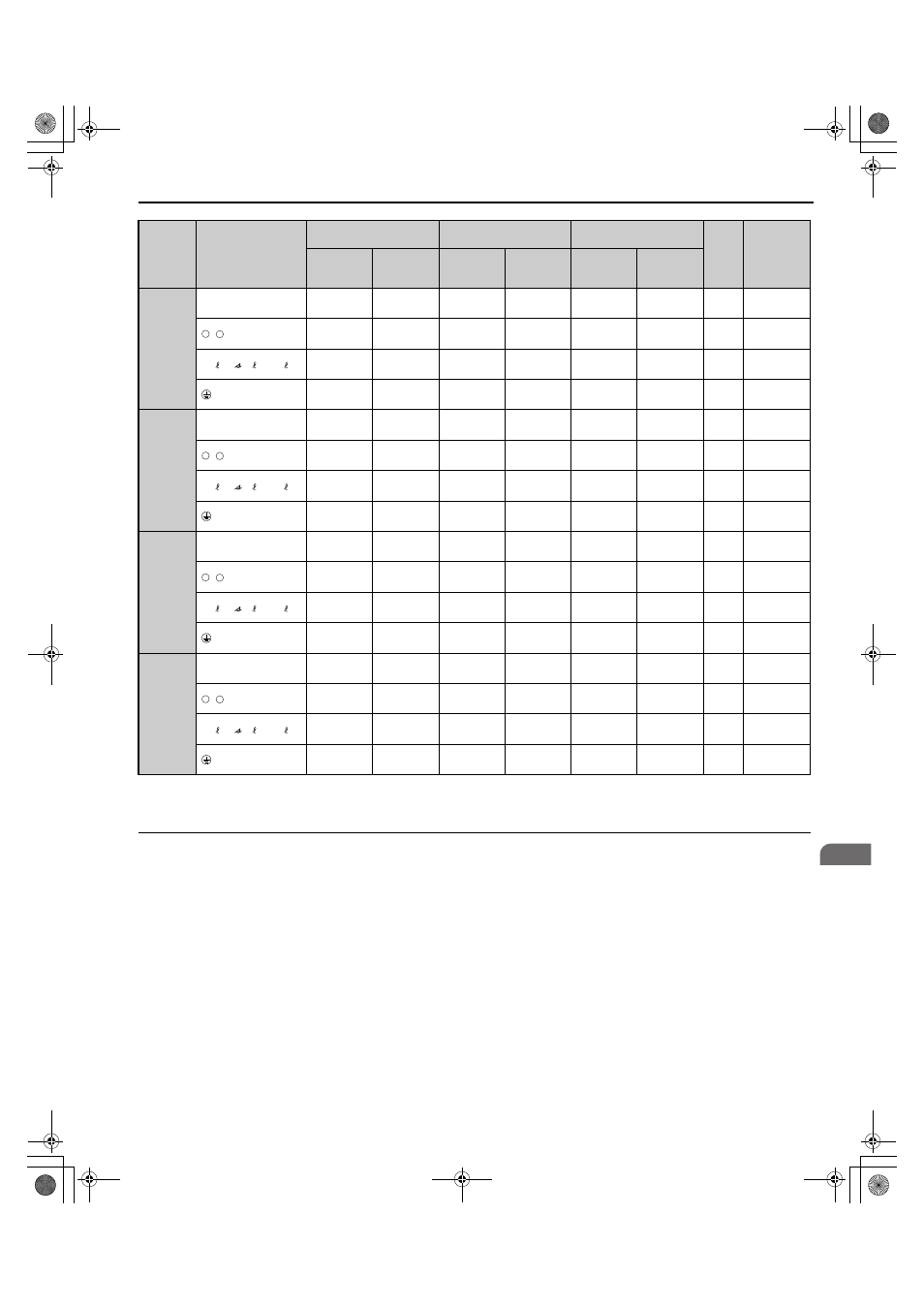
3.8 Main Circuit Wiring
YASKAWA ELECTRIC TOEP C710656 08B YASKAWA Power Regenerative Unit - R1000 Instruction Manual
55
El
ec
tr
ical
I
n
st
al
lat
ion
3
◆ Ground Wiring
Follow the precautions below when wiring the ground for one regenerative unit or a series of regenerative units.
WARNING! Electrical Shock Hazard. Always use a ground wire that complies with technical standards on electrical equipment and
minimize the length of the ground wire. Improper equipment grounding may cause dangerous electrical potentials on equipment
chassis, which could result in death or serious injury.
WARNING! Electrical Shock Hazard. Be sure to ground the regenerative unit ground terminal (200 V class: ground to 100
Ω or less;
400 V class: ground to 10
Ω or less). Improper equipment grounding could result in death or serious injury by contacting ungrounded
electrical equipment.
NOTICE: Do not share the ground wire with other devices such as welding machines or large-current electrical equipment. Improper
equipment grounding could result in regenerative unit or equipment malfunction due to electrical interference.
NOTICE: When using more than one regenerative unit, ground multiple regenerative units according to instructions. Improper
equipment grounding could result in abnormal operation of regenerative unit or equipment.
4A0105
R/L1,S/L2,T/L3
50
50 to 150
2/0
2/0 to 300
50
50 to 150
M10
18.0 to 23.0
(159 to 204)
,
80
80 to 150
4/0
4/0 to 300
70
70 to 150
M10
18.0 to 23.0
(159 to 204)
r1/ 11, 1/ 21,t1/ 31
2
2 to 5.5
14
14 to 10
2.5
2.5 to 6
M4
1.1 to 1.2
(9.7 to 10.6)
38
38 to 150
1
1 to 300
25
25 to 150
M10
18.0 to 23.0
(159 to 204)
4A0150
R/L1,S/L2,T/L3
100
100 to 150
250
250 to 300
95
95 to 240
M12
32.0 to 40.0
(283 to 354)
,
150
150 to 325
3/0
×
2P
3/0 to 600
150
150 to 240
M12
32.0 to 40.0
(283 to 354)
r1/ 11, 1/ 21,t1/ 31
2
2 to 5.5
14
14 to 10
2.5
2.5 to 6
M4
1.1 to 1.2
(9.7 to 10.6)
60
60 to 150
1/0
1/0 to 300
25
25 to 150
M12
32.0 to 40.0
(283 to 354)
4A0210
R/L1,S/L2,T/L3
80
× 2P
80 to 325
3/0
×
2P
3/0 to 600
95
×
2P
95 to 240
M12
32.0 to 40.0
(283 to 354)
,
80
× 2P
80 to 325
4/0
×
2P
4/0 to 600
95
×
2P
95 to 150
M12
32.0 to 40.0
(283 to 354)
r1/ 11, 1/ 21,t1/ 31
2
2 to 5.5
14
14 to 10
2.5
2.5 to 6
M4
1.1 to 1.2
(9.7 to 10.6)
60
60 to 180
2/0
2/0 to 350
95
95 to 240
M12
32.0 to 40.0
(283 to 354)
4A0300
R/L1,S/L2,T/L3
100
× 2P
100 to 325
250
×
2P
250 to 600
95
×
2P
95 to 240
M12
32.0 to 40.0
(283 to 354)
,
150
× 2P
150 to 325
400
×
2P
400 to 600
120
×
2P
120 to 150
M12
32.0 to 40.0
(283 to 354)
r1/ 11, 1/ 21,t1/ 31
2
2 to 5.5
14
14 to 10
2.5
2.5 to 6
M4
1.1 to 1.2
(9.7 to 10.6)
60
× 2P
60 to 180
4/0
4/0 to 350
95
95 to 240
M12
32.0 to 40.0
(283 to 354)
<1> Gauges listed here are for use in Japan.
<2> Gauges listed here are for use in the United States.
<3> Gauges listed here are for use in Europe and China.
Model
Terminal
For Asia
<1>
For U.S.A.
<2>
For Europe and China
<3>
Screw
Size
Tightening
Torque
Nxm
(lbxin.)
Recomm.
Gauge
mm
2
Applicable
Gauge
mm
2
Recomm.
Gauge
AWG
Applicable
Gauge
AWG
Recomm.
Gauge
mm
2
Applicable
Gauge
mm
2
–
+
–
+
–
+
–
+
TOEP_C710656_08B_1_0.book 55 ページ 2015年2月5日 木曜日 午前10時7分